2
3
1
6 4
10
9
58
7
11
12
13
14
15
16
17
p. 14 - Manual FA00995-EN - 01/2018 - © CAME S.p.A. -
Translation of the original instructions
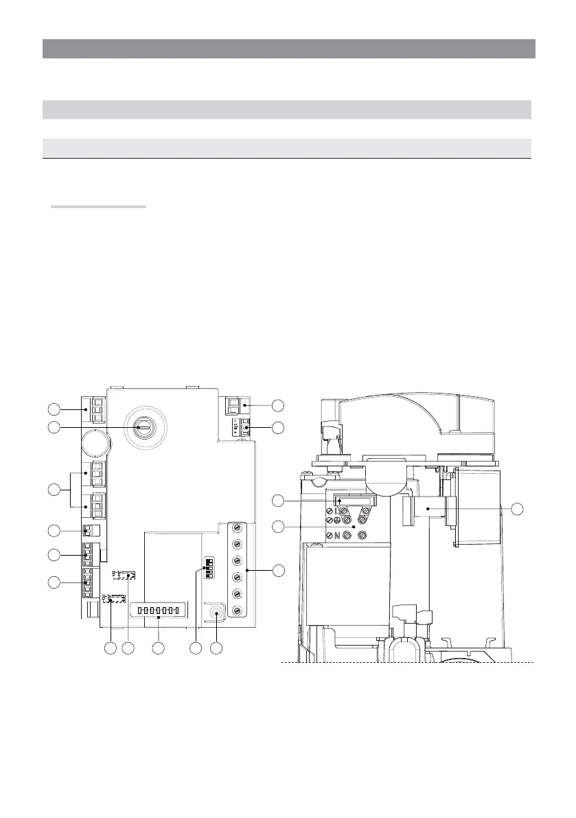
Description of parts
1. Transformer terminals
2. RGP1 module terminal
3. Trimmer
4. Programming button
5. DIP-SWITCH
6. Alert LED
7. R800 card connector
8. AF card connector
9. Safety-device terminals
10. Control devices terminals
11. Keypad selector terminal
12. Terminal boards gearmotors
13. Accessories / board fuse
14. Warning device terminals
15. Line fuse
16. Power supply terminal board
17. Housing for the RGP1 module
CONTROL CARD
⚠
Before working on the control panel, cut off the mains power supply and remove any batteries.
All wiring connections are quick-fuse protected.
Fuses ZL60
HD Analog 2 A-F = 230 V
Accessories / control board 2 A-F
 Loading...