p. 19 - Manual FA01313-EN - 02/2019 - © CAME S.p.A. - The contents of this manual may change, at any time, and without notice. - Original instructions
Input voltage
Make sure the mains power supply is disconnected during all installation procedures.
Before working on the control panel, cut off the mains power supply and remove any batteries.
Turn on and off the power supply to the control panel always acting on the switch.
Connecting to the electrical network Accessories power supply output
2 3
5
1
4
1 Button for turning the device on/off.
2 Apply the ferrite supplied to the power-supply cable.
Ferrite type p.n. ECQK922091.
The cable must pass 2 times through the ferrite (2 turns).
3 Connect the power cable as shown.
4 Fuse for cartridge heater or fan
5 Line fuse
10 11 E1 E6 TS 1 2 3 3
E
The output normally delivers 24 V DC.
The sum of the connected accessories
input must not exceed 40 W.
Signalling devices
1 Additional light
Increases illumination in the maneuvering area.
Maximum contact capacity 10 - E1
24 V DC - 20 W
2 Additional flashing light
It flashes during the operator opening and closing
phases.
Maximum contact capacity 10 - E1
24 V DC - 20 W
3 Operator status warning light
It warns of the operator status.
Maximum contact capacity 10 - 5
24 V DC - 3 W
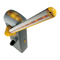
4 RGB LED strip and/or RGB corona
Maximum capacity 13.5 W
Flashing red LEDs: Operator in movement.
Green LEDs on: Operator open.
Red LEDs on: Operator closed.
Red LED flashing fast: Inspection hatch open,
gearmotor unlocked or boom drop-away.
A B GND A B GND RGB
2
10
S1
GND
AB
11 E1 E6 TS 1 2 3 3P 4 5 7 2 CX CY CZ
FA
FC
FCA CM1 FCC CM2
MOTOR
BLOCK
+
-
1
2
3
4
 Loading...