Do you have a question about the CAME GGT80AGS and is the answer not in the manual?
Crucial safety guidelines for safe installation and operation.
Precautions to be read and followed by end-users for safe operation.
Highlights potential hazards and user safety warnings.
Guidelines for responsible product dismantling and waste disposal.
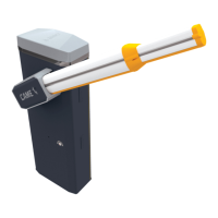
Explains symbols and provides a brief overview of the barrier models.
Detailed specifications, including power, temperature, and torque for models.
Lists fuse ratings for different components and models.
Identifies and labels all external and internal parts of the barrier system.
Details the various terminals and connectors on the control board.
Provides dimensions and minimum cable thicknesses for installation.
Details resistance classes and wind pressure ratings for different boom lengths.
Steps before installation, including foundation prep and wiring.
Instructions for preparing and setting the foundation frame and anchoring plate.
Steps for accessing the internal components and preparing the barrier.
Securing the barrier to the foundation frame.
Step-by-step guide to reverse the boom's opening side.
Instructions for inserting reinforcement and attaching the boom.
Guide to selecting the correct hole for balance spring fixing based on passage width.
Detailed steps for correctly installing the balance spring.
Procedure to adjust spring tension for proper boom stabilization at 45°.
Setting the boom's horizontal travel limits using mechanical stops.
Adjusting the boom's vertical angle using mechanical stops.
Guidelines for routing cables safely to avoid damage.
Instructions for connecting the barrier to the mains power supply.
Details output capacity for various devices and accessories.
Information on connecting devices via the CXN BUS system.
Explains various control devices and their connections to the board.
Describes additional lights, beacons, and status indicators.
Information on connecting photocells and other safety inputs.
Wiring diagrams for DIR/DELTA-S photocell types.
Wiring diagrams for DXR/DLX photocell types.
Explains the operation of the ESC, <>, and ENTER buttons.
Steps to follow after electrical connections for commissioning.
Introduces the main functions accessible via the control panel.
Assigning functions to CX, CY, and CZ inputs for safety and control.
Testing safety devices and configuring hold-to-run functionality.
Configuring obstacle detection and open warning light behavior.
Configuring courtesy light, automatic closure, and pre-flashing times.
Adjusting opening/closing speeds and travel sensitivity for obstructions.
Setting up RSE card functions for paired or remote connections.
Saving/reading data, transferring parameters, and setting maintenance alerts.
Configuring flashing beacon timing and RSE communication speed.
Setting up status reports and emergency battery operation.
Adding, removing, or removing all users and their functions.
Setting radio coding types and defining the boom length.
Performing motor tests and initiating travel self-learning.
Restoring factory settings and managing system access passwords.
Assigning functions to inputs via the Photocell BUS.
Saving and loading system data using a memory roll card.
Completing the installation with final checks and operations.
Connecting two operators for synchronized control.
Configuring the MASTER operator for paired mode.
Illustrates operating modes for paired barriers.
Connecting two operators for sequential operation.
Configuring the RSE_1 function for alternate mode.
Illustrates operating modes for alternate barriers.
Mean Cycles Between Failures (MCBF) and accessory impact on cycle life.
Recommended maintenance checks and replacement intervals.
Explains various error codes displayed by the system and their meanings.
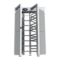
| Type | Full Height Turnstile |
|---|---|
| Material | AISI 304 Stainless Steel |
| Width | 1500 mm |
| Weight | 350 kg |
| Operating Temperature | -25°C to +70°C |
| Passage Width | 600mm |
| Rotation direction | Bidirectional |
| Throughput | 30 people/minute |