3
TF2101,TF2111,TQ3010,TQ3011,TX2101,TX2118
Installation(Continued)
Donotlocatethe
compressorair
inletnearsteam,paintspray,
sandblastareasoranyothersource
ofcontamination.
NOTE:Ifcompressoroperatesinahot,
moistenvironment,supplycompressor
pumpwithclean,dryoutsideair.Supply
airshouldbepipedinfromexternal
sources.Fortwo-stagecompressors
only,useadapterkit(TF060502AV)
toconnectpipingtocompressor.Two
adapterkitsareneededfortwo-stage
10and15HPunits.
TANKMOUNTING
Thetankshouldbeboltedintoaflat,
even,concretefloororonaseparate
concretefoundation.Vibrationisolators
shouldbeusedbetweenthetankleg
andthefloor.ModelMP367700AJ
isolatorpadsarerecommendedfor
horizontalunits.ModelMP345700AJ
isolatorpadsarerecommendedfor
verticalunits.Whenusingisolator
pads,donotdrawboltstight.Allow
thepadstoabsorbvibrations.When
isolatorsareused,aflexiblehoseor
couplingshouldbeinstalledbetween
thetankandservicepiping.
Failure
toproperlyinstallthe
tankcanleadtocracks
attheweldedjointsand
possiblebursting.
PIPING
Neveruseplastic
(PVC)pipefor
compressedair.Seriousinjuryor
deathcouldresult.
Anytube,pipeorhoseconnectedto
theunitmustbeabletowithstandthe
temperaturegeneratedandretainthe
pressure.Allpressurizedcomponents
oftheairsystemmusthaveapressure
ratinghigherthanorequaltothe
200psifortwo-stagecompressorsor
150psiforsinglestagecompressors
ASMEsafetyvalvesetting.
Incorrectselectionandinstallationof
anytube,pipeorhosecouldresultin
burstingandinjury.Connectpiping
systemtotankusingthesamesize
fittingasthedischargeport.
INSTALLINGASHUT-OFFVALVE
Ashut-offvalveshouldbeinstalled
onthedischargeportofthetankto
controltheairflowoutofthetank.
Thevalveshouldbelocatedbetween
thetankandthepipingsystem.
Neverinstalla
shut-offvalve
betweenthecompressorpump
andthetank.Personalinjuryand/
orequipmentdamagemayoccur.
Neverusereducersindischarge
piping.
Whencreatingapermanentlyinstalled
systemtodistributecompressedair,
findthetotallengthofthesystemand
selectpipesizefromthechart.Bury
undergroundlinesbelowthefrostline
andavoidpocketswherecondensation
cangatherandfreeze.
Applyairpressuretothepiping
installationandmakesurealljointsare
freefromleaksBEFOREunderground
linesarecovered.Beforeputtingthe
compressorintoservice,findandrepair
allleaksinthepiping,fittingsand
connections.
Chart1:MinimumPipeSizefor
CompressedAirLine(ininches)
LengthOfPiping
System(infeet)
CFM 25 50 100 250
10 1/2 1/2 3/4 3/4
20 3/4 3/4 3/4 1
40 3/4 1 1 1
60 3/4 1 1 1
100 1 1 1 1-1/4
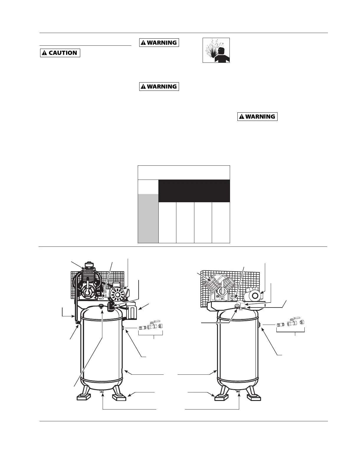
DrainValve
IsolationPad
(availableseparately)
Tank
Discharge
Port
TankShut-OffValve
(availableseparately)
Discharge
Port
TankShut-OffValve
(availableseparately)
Pressure
Gauge
Pressure
Gauge
FactoryMounted
MagneticStarter
(notonallunits)
Pressure
Switch
Pressure
Switch
Safety
Valve
Motor
Motor
Pump
Pump
Check
Valve
Discharge
Tube
Discharge
Tube
SafetyValve
Access
Figure1-VerticalUnitIdentification
 Loading...