Installation(Continued)
WIRING
Allwiring
andelectrical
connectionsmustbeperformedby
aqualifiedelectrician.Installations
mustbeinaccordancewithlocal
andnationalcodes.
Overheating,short
circuitingandfire
damagewillresultfrominadequate
wiring.
Wiringmustbeinstalledinaccordance
withNationalElectricalCodeandlocal
codesandstandardsthathavebeenset
upcoveringelectricalapparatusand
wiring.Theseshouldbeconsultedand
localordinancesobserved.Becertain
thatadequatewiresizesareused,and
that:
1. Serviceisofadequateampere
rating.
2. Thesupplylinehasthesame
electricalcharacteristics(voltage,
cyclesandphase)asthemotor.
3. Thelinewireisthepropersize
andthatnootherequipmentis
operatedfromthesameline.The
chartgivesminimumrecommended
wiresizesforcompressor
installations.
Recommendedwiresizesmaybelarger
thantheminimumsetupbylocal
ordinances.Ifso,thelargersizewire
shouldbeusedtopreventexcessive
linevoltagedrop.Theadditionalwire
costisverysmallcomparedwiththe
costofrepairingorreplacingamotor
electrically“starved”bytheuseof
supplywireswhicharetoosmall.
GROUNDING
Improperlygrounded
electricalcomponents
areshockhazards.
Makesureallthecomponents
areproperlygroundedtoprevent
deathorseriousinjury.
Thisproductmustbegrounded.
Groundingreducestheriskofelectrical
shockbyprovidinganescapewire
fortheelectriccurrentifshortcircuit
occurs.Thisproductmustbeinstalled
andoperatedwithapowercordor
cablethathasagroundingwire.
MOTORHOOKUPANDSTARTER
INSTALLATION
Branchcircuitprotectionmustbe
providedasspecifiedintheUnited
StatesNationalElectricalCode,Chapter
2,“WiringDesignandProtection.”
Article210,usingtheapplicablearticle
“ForMotorsandMotorControllers,”
(Article430,Table430-152).
IMPORTANT:Overloadprotection
isrequiredforallmotors.Certain
motorshavethisprotectionbuilt-in.
Todetermineifamotorhasbuilt-in
overloadprotection,refertotheframe
sizeonthemotornameplate.
MotorswithframesizeR56HZ,Y56Y
orL143Tincludebuilt-inoverload
protection.Noadditionalprotectionis
required.UseFigure3wiringdiagram.
Motorswithframesizes184T,215T,
254Tor284Tdonothavebuilt-in
overloadprotection.Amagnetic
starterisrequired.UseFigure4wiring
diagram.
Tochangetothealternatevoltage
onthreephasemotorswith230/460
ratings:
1. Rewiremotorperdataplateon
motororinstructionsheet.
2. Checkelectricratingofmagnetic
starterandreplacethermal
overloadelementsormagnetic
starterasrequired.Thevoltageand
amperageratingsarelistedonthe
motornameplate.
DIRECTIONOFROTATION
NOTE:Improperrotationwillresultin
reducedunitlife.
Thedirectionofrotationmustbe
counterclockwise(asshownbythe
arrowontheflywheel)whilefacing
theflywheelsideofthepump.The
motornameplatewillshowwiring
informationforcounterclockwise
rotation.
Theproperdirectionisvery
important.Thedirectionofrotation
of3phasemotorscanbereversed
byinterchanginganytwomotor-line
leads.Forsinglephasemotors,referto
themotornameplate.
OperatingInstructions
4
Chart2:MinimumWireSize
Use75°CCopperWire
Single
Phase
Three
Phase
HP
Amps
230V
208/
230V
460/
575V
SPL
Upto22.0
10
AWG
5.0
8
AWG
12
AWG
14
AWG
7.5
8
AWG
10
AWG
12
AWG
10.0
8
AWG
12
AWG
15.0
6
AWG
10
AWG
25.0
3
AWG
8
AWG
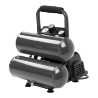
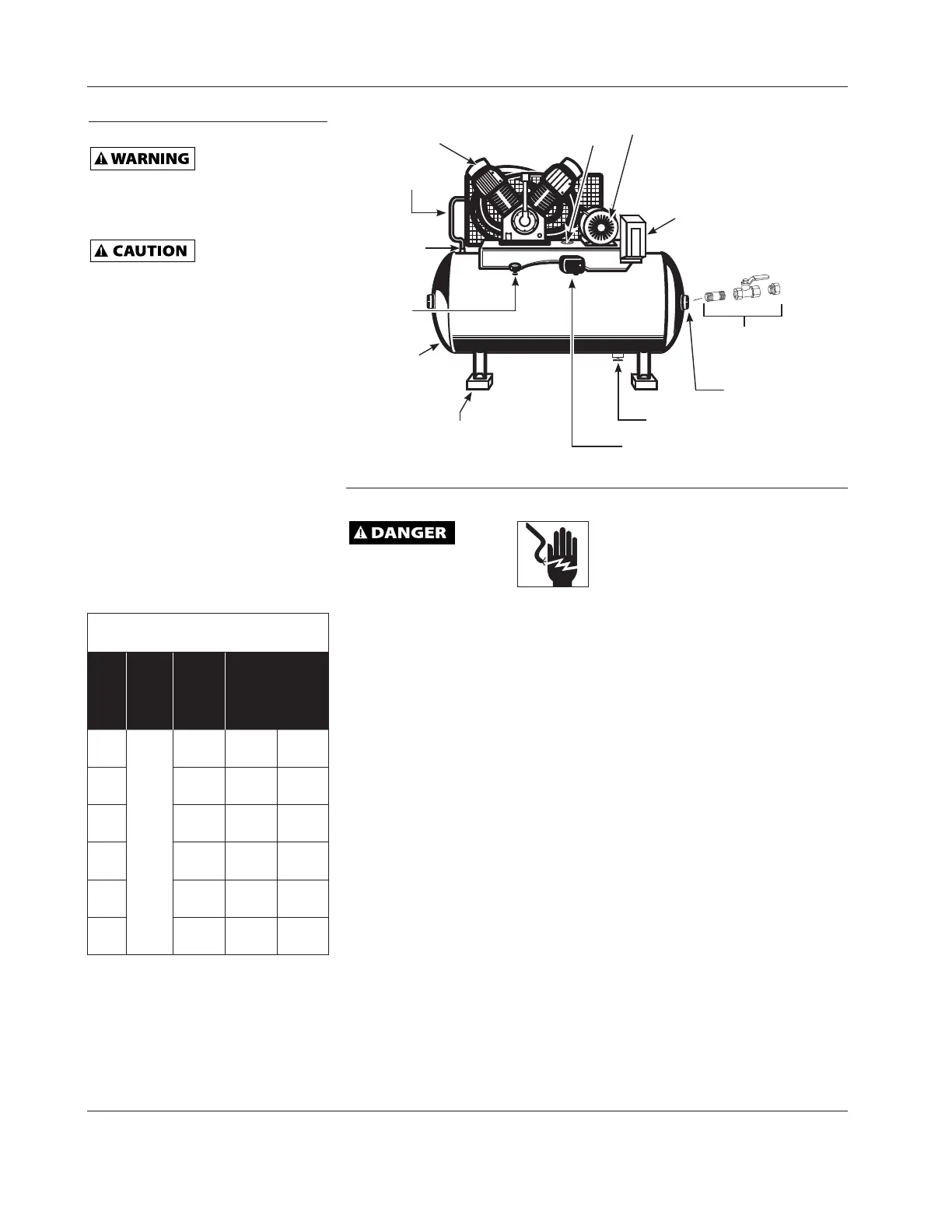
IsolationPad
(availableseparately)
Tank
TankShut-OffValve
(availableseparately)
FactoryMounted
MagneticStarter
(notonallunits)
Pump
Discharge
Tube
Motor
SafetyValve
Access
Figure2-HorizontalUnitIdentification
DrainValve
DischargePort
PressureSwitch
Pressure
Gauge
Check
Valve
 Loading...