EasyManua.ls Logo

Campbell Hausfeld WG2020 User Manual

Campbell Hausfeld WG2020
36 pages
To Next Page IconTo Next Page
Page #1 background imageLoading...
Page #1 background image
Heat Circuit Breaker or
Selector Slow Blow Fuse
Low 15 amp
High 20 amp
Please read and save these instructions. Read carefully before attempting to assemble, install, operate or maintain the product described.
Protect yourself and others by observing all safety information. Failure to comply with instructions could result in personal injury and/or
property damage! Retain instructions for future reference.
IN212800AV 7/99
Operating Instructions & Parts Manual Model WG2020
Wire Feed
Arc Welder
BUILT TO LAST
TM
The Campbell Hausfeld WG2020 is a 70
amp, single phase 115 volt input, wire
feed arc welding machine equipped
with infinite wire speed control to
accurately select proper wire feed rate
needed for various welding conditions.
Internal components are
thermostatically protected.
This welding system is designed for use
with the Flux Core Arc Welding (FCAW)
or the Gas Metal Arc Welding (GMAW)
process. As delivered from the factory,
this welder can weld with .024” (.6mm)
to .035” (.9mm) diameter wire. A starter
spool of flux-cored wire is included.
1
2
4
5
6
3
1. Work Clamp - connect to work piece.
2. Wire Feed Gun
3. Power Cord - plug into 115 volt
outlet.
4. On/Off Switch - illuminates if
thermostat has automatically shut
unit off.
5. Infinite Wire Speed Control - turns
clockwise to increase wire speed and
counterclockwise to decrease wire
speed.
6. Heat Selector - Selects welding
power. Four selections are possible;
low 1, low 2, high 1 and high 2.
Danger means a
hazard that will
cause death or serious injury if the
warning is ignored.
Warning means a
hazard that could
cause death or serious injury if the
warning is ignored.
Caution means a
hazard that may
cause minor or moderate injury if the
warning is ignored. It also may mean a
hazard that will only cause damage to
property.
NOTE: Note means any additional
information pertaining to the product
or its proper usage.
Figure 1 -
Welder Components
and Controls
See page 7 for supply cable
replacement instructions.
Q
U
A
L
I
T
Y
A
S
S
U
R
A
N
C
E
P
R
O
G
R
A
M
Need
Assistance?
Call Us First!
1-800-746-5641
Unpacking
All welding accessories for the
welder are inside the wire feed
compartment. Lift and remove wire
feed cover to find handle,
workclamp, etc. When unpacking,
inspect carefully for any damage that may
have occurred during transit. Make sure
any loose fittings and screws, etc. are
tightened before putting unit into service.
This equipment
requires a dedicated
115 volt circuit. Refer to the following
chart for correct circuit breaker or fuse
rating. Do not run other appliances, lights
or tools on this circuit while operating
this equipment. Extension cords are not
recommended. Blown fuses and tripped
circuit breakers can result from failure to
comply with this recommendation.
Description
CIRCUIT REQUIREMENTS
COMPONENTS AND CONTROLS
General Safety
For parts, product & service information
visit www.campbellhausfeld.com
Question and Answer IconNeed help?

Do you have a question about the Campbell Hausfeld WG2020 and is the answer not in the manual?

Campbell Hausfeld WG2020 Specifications

General IconGeneral
Input Voltage120V
Input Current20A
Output Current Range30-90A
Welding ProcessesMIG
Duty Cycle20% @ 90A

Summary

Description

Unpacking

CIRCUIT REQUIREMENTS

CAUTION

Equipment requires a dedicated 115 volt circuit. Extension cords are not recommended.

COMPONENTS AND CONTROLS

1. Work Clamp

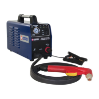
Connects to the work piece for completing the circuit.

2. Wire Feed Gun

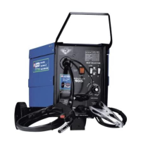
The tool used to deliver wire and welding arc.

3. Power Cord

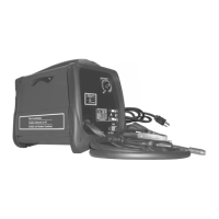
Connects the welder to the power supply.

4. On/Off Switch

Illuminates if the thermal switch has shut the unit off.

5. Infinite Wire Speed Control

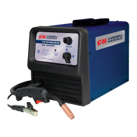
Adjusts wire feed rate clockwise to increase, counterclockwise to decrease.

6. Heat Selector

Selects welding power with four possible selections.

General Safety

DANGER: General Safety

Indicates a hazard that will cause death or serious injury if warning is ignored.

WARNING: General Safety

Indicates a hazard that could cause death or serious injury if warning is ignored.

CAUTION: General Safety

Indicates a hazard that may cause minor or moderate injury or property damage.

NOTE: General Safety

Provides additional information pertaining to the product or its proper usage.

General Safety (Continued)

WARNING: Fire Extinguisher

Always keep a fire extinguisher accessible while performing arc welding operations.

WARNING: Electric Shock

Improper use can cause electric shock, injury, and death. Take precautions.

CAUTION: Welding Wire Live

The welding wire is live whenever the welder is turned on.

WARNING: Arc Welding Operations

Never look at arc welding operations without eye protection.

WARNING: Sparks and Heat

Sparks and heat can cause severe burns. Use protective gloves and clothing.

WARNING: Flammable Materials

Heat and sparks can ignite flammable materials. Remove flammables within 35 feet.

General Safety (Continued)

WARNING: Flammable Vapors

Do not weld in areas where flammable or explosive vapors may be present.

WARNING: Fire Hazard Containers

Do not weld on containers that have contained flammable materials.

WARNING: Cylinder Explosion

Arc welding closed cylinders can cause explosion if not properly vented.

WARNING: Toxic Fumes

Do not breathe fumes; use respirator if ventilation is inadequate.

WARNING: Electromagnetic Field

EMF may interfere with electronic devices like pacemakers.

DANGER: Cylinder Damage

Gas cylinders can explode if damaged. Handle carefully.

DANGER: Flammable Gases

Never use flammable gasses with MIG welders.

WARNING: Lifting Cylinders

Never lift cylinders by their valves or caps.

Installation

LOCATION

Select a clean, dry, well-ventilated area for optimal performance and longevity.

Assembly

Instructions for assembling accessories like handle and work clamp.

HANDLE AND BASE ASSEMBLY

Steps for attaching the handle and cylinder base to the unit.

WORK CLAMP

Procedure for attaching the work clamp to the welder's cord.

WIRE INSTALLATION

Steps for loading and preparing the welding wire.

WARNING: Welding Power Applied

Welding power may be applied to terminals even when the trigger is not activated.

Assembly (Continued)

Shielding Gas Preparation

Guidelines for preparing and connecting shielding gas cylinders.

DANGER: Gas Cylinder Handling

Improper handling can cause serious injury or death. Secure cylinders.

GAS TYPES

Describes common gases used for gas metal arc welding.

REGULATOR

Explains the function and selection of the gas regulator.

HOOKUP PROCEDURE

Steps for connecting the gas cylinder, regulator, and hose.

WARNING: Cylinder Pressure

Cylinder gas is under high pressure; point outlet away from yourself.

Assembly (Continued)

HOOKUP PROCEDURE (Continued)

Detailed steps for connecting gas components and checking for leaks.

Operation

MANUAL: Read Instructions

Emphasizes reading and complying with all safety and welding guidelines.

WARNING: Persons Operating

All personnel must wear protective welding gear.

WARNING: Galvanized Materials

Toxic fumes from galvanized materials; follow specific precautions.

Maintenance

WARNING: Disconnect Power

Disconnect power and turn off machine before inspecting or servicing.

BEFORE EVERY USE

Checks to perform before each use, including cables and gun tip.

EVERY 3 MONTHS

Periodic maintenance tasks like cleaning ventilation and drive roll.

Consumable and Wear Parts

Lists parts requiring routine maintenance and replacement.

Maintenance (Con't.)

CHANGING WIRE SIZES

How to change drive roll and contact tip for different wire diameters.

Supply Cable Replacement

Steps for safely replacing the welder's power supply cable.

Welding Guidelines

General

Explains FCAW and MIG processes, arc formation, and shielding.

Arc Welding Basics

Five basic techniques affecting weld quality: selection, heat, angle, speed.

HEAT SETTING

How to adjust heat/voltage based on wire, position, and thickness.

WIRE TYPE AND SIZE

Factors for choosing wire type and size, and AWS recommendations.

Welding Guidelines (Continued)

WELD ANGLE

Explains travel and work angles for proper penetration and bead formation.

WIRE SPEED

How to tune wire speed for optimal melting and arc quality.

TRAVEL SPEED

Affects bead width and appearance; determined by wire, amperage, and material.

SLAG REMOVAL

Procedure for removing slag after welding with flux-cored wire.

WARNING: Slag Removal

Wear safety glasses and protective clothing when removing slag.

WELDING POSITIONS

Discusses flat, horizontal, vertical, and overhead welding positions.

Welding Guidelines (Continued)

WELD PASSES

Guidance on using multiple passes for joints and beveling edges.

PUSH VS PULL TECHNIQUE

How to orient the gun nozzle for different materials and penetration.

Wiring Schematic

Troubleshooting Chart: Welder

Troubleshooting Chart: Welds

Replacement Parts

Parts List

Detailed list of replacement parts with reference numbers and part numbers.

Glossary of Welding Terms

Limited 5-3-1 Warranty

Related product manuals