EasyManua.ls Logo

Campbell Hausfeld WG3060 User Manual

Campbell Hausfeld WG3060
48 pages
To Next Page IconTo Next Page
Page #1 background imageLoading...
Page #1 background image
Please read and save these instructions. Read carefully before attempting to assemble, install, operate or maintain the product described.
Protect yourself and others by observing all safety information. Failure to comply with instructions could result in personal injury and/or
property damage! Retain instructions for future reference.
IN211104AV 9/99
Operating Instructions & Parts Manual Models WG3000 and WG3060
Wire Feed
Arc Welder
BUILT TO LAST
TM
This line of Campbell Hausfeld wire feed
welders is designed to be used on
standard 115V household current. The
welders are equipped with infinite wire
speed control to accurately select the
proper wire feed rate needed for various
welding conditions. Internal components
are thermostatically protected.
These welders are designed for use with
Flux Core Arc Welding (Gasless) or Gas
Metal Arc Welding (Mig) process. As
delivered from the factory, this welder
can weld with .024” (.6 mm) to .035”
(.9 mm) diameter wire. A starter spool
of .035” (.9 mm) flux-cored wire and a
.040 tip are included.
Unpacking
Some welder components may be
found in the wire feed compartment.
When unpacking, inspect carefully for
any damage that may have occurred
during transit. Report any damaged or
missing items by calling (800) 746-5641.
Circuit Requirements
This equipment
requires a dedi-
cated 115 volt circuit. Refer to the
following chart for the correct circuit
breaker or fuse rating. Do not run
other appliances, lights, or tools on
this circuit while operating this
equipment. Extension cords are not
recommended. Blown fuses and tripped
circuit breakers can result from failure
to comply with this recommendation.
Components and Controls
1. Work Clamp - connect to work
piece.
2. Wire Feed Gun with .040 tip
3. Power Cord - plug into 115 volt
outlet.
4. On/Off Switch
5. Infinite Wire Speed Control -
turns clockwise to increase wire
speed and counterclockwise to
decrease wire speed.
6. Heat Selector - Selects welding
power. Four selections are possible
7. Polarity Hook-up - Attach torch
cable to (+) for MIG and (-) for flux
core wire.
Heat Circuit Breaker or
Selector Slow Blow Fuse
Danger means a
hazard that will
cause death or serious injury if the
warning is ignored.
Warning means a
hazard that could
cause death or serious injury if the
warning is ignored.
Caution means a
hazard that may
cause minor or moderate injury if the
warning is ignored. It also may mean a
hazard that will only cause damage to
property.
NOTE: Note means any additional
information pertaining to the product
or its proper usage.
MODEL WG3000
Low (1-2) 15 amp
High (3-4) 20 amp
Q
U
A
L
I
T
Y
A
S
S
U
R
A
N
C
E
P
R
O
G
R
A
M
Need
Assistance?
Call Us First!
1-800-746-5641
Description
MODEL WG3060
1
1
2
2
3
3
4
4 & 6
5
5
6
7
Figure 1
General Safety
© 1999 Campbell Hausfeld / Scott Fetzer
For parts, product & service information
visit www.campbellhausfeld.com
7
Question and Answer IconNeed help?

Do you have a question about the Campbell Hausfeld WG3060 and is the answer not in the manual?

Campbell Hausfeld WG3060 Specifications

General IconGeneral
Input Voltage120V
Input Current20A
Welding ProcessMIG (GMAW)
Duty Cycle20% at 90A
Maximum Welding Thickness1/8 in. (3.2 mm)
Weight38 lb (17.2 kg)
Amperage Range30-90 A
Wire Size0.030 in. (0.8 mm)

Summary

Description and Components Overview

Unpacking and Circuit Requirements

Details on how to unpack the welder and check for damage, plus electrical circuit requirements.

Component Identification and Function

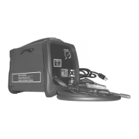
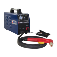
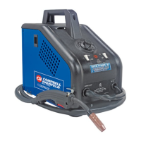
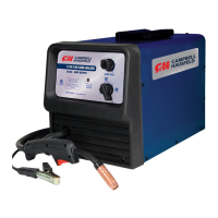
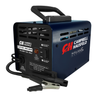
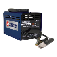
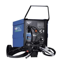
Identification and function of key components like work clamp, gun, cord, and controls.

General Safety Classifications

Explanation of hazard classifications: DANGER, WARNING, CAUTION, and NOTE.

General Safety Precautions

Torch Live Warning and Fire Safety

Warning that the torch has current when ON and advice to keep a fire extinguisher accessible.

Electrical and Personal Safety

Precautions against electric shock and injury from sparks, light, heat, and fumes.

Flammable Materials and Cylinder Hazards

Warnings about igniting flammable materials and risks from welding closed cylinders.

Advanced Safety and Installation Guidance

Fume Hazards and Gas Cylinder Safety

Warnings about toxic fumes, gas cylinder dangers, and handling.

Electromagnetic Interference and Cable Safety

Warnings on electromagnetic fields and safe cable handling.

Installation Location and Power Requirements

Guidance on choosing location, ventilation, and power supply connection.

Assembly Procedures

Handle, Wheel, and Bracket Assembly

Steps for assembling the handle, wheels, axle, and gas cylinder bracket.

Foot and Work Clamp Assembly

Instructions for assembling the foot and the work clamp.

Welding Wire Installation and Routing

Detailed steps for installing welding wire and routing it through the system.

Torch Nozzle and Wire Size Details

Information on the torch nozzle and wire size compatibility.

Shielding Gas and Operation Setup

Wire Size, Polarity, and Helmet Assembly

Settings for wire size, polarity, and instructions for helmet assembly.

Compressed Gas Cylinder Safety

Safety warnings regarding compressed gas cylinders and high pressure.

Shielding Gas Hookup and Regulator Use

Procedure for connecting shielding gas and using the regulator.

Operational and Maintenance Guidelines

Pre-Operation Safety and Wire Handling

Safety checks before operation and guidance on wire handling.

Welding Process Setup and Execution

Steps for setting heat/speed, and starting the welding process.

Safety Precautions and Routine Maintenance

Maintenance safety, disconnection, routine checks, and wear parts.

Welding Guidelines and Procedures

Nozzle Selection and Wire Size Changes

Information on nozzles and changing wire sizes for different applications.

General Welding Process Overview

Explanation of welding processes and weld components.

Arc Welding Basics and Heat Setting

Fundamental techniques affecting weld quality and heat setting adjustments.

Advanced Welding Techniques

Wire Type, Size, and Weld Angle

Guidance on choosing wire, and the importance of weld angle.

Wire Speed and Travel Speed Tuning

Importance of tuning wire and travel speed for optimal welds.

Slag Removal and Welding Positions

Procedure for removing slag and description of welding positions.

Weld Appearance and Cable Replacement

Weld Appearance, Passes, and Techniques

Visual guide to welds, weld passes, and push vs. pull techniques.

Aluminum Welding and Cable Replacement

Specific requirements for aluminum welding and supply cable replacement.

Troubleshooting Guides

Welder Output and Wire Feed Issues

Steps for diagnosing and resolving no output, wire feed, and aluminum wire problems.

Weld Bead Quality and Penetration Issues

Steps for diagnosing and resolving issues with weld bead thickness, edges, penetration, and sputtering.

Limited Warranty Information

Warranty Duration and Coverage Details

Information on warranty duration for components and what is covered.

Warranty Exclusions and Responsibilities

Details on what is not covered and the responsibilities of the warrantor and purchaser.

WG3000 Wiring Diagram

WG3060 Wiring Diagram

Replacement Parts Information

Parts Correspondence and Optional Items

Instructions for addressing parts correspondence and lists of optional wire/tips.

Glossary of Welding Terms

AC or Alternating Current

Definition of electric current that reverses direction periodically.

Arc Length

Definition of the distance from electrode end to workpiece contact point.

Base Metal

Definition of the material to be welded.

Butt Joint

Definition of a joint between two members aligned in the same plane.

Crater

Definition of a pool or pocket formed by arc contact with base metal.

DC or Direct Current

Definition of electric current flowing in only one direction.

DC Reverse Polarity

Definition of electrode connected to positive pole, directing heat to electrode.

DC Straight Polarity

Definition of electrode connected to negative pole, directing heat to workpiece.

Electrode

Definition of a coated metal wire similar to the material being welded.

Fillet Weld

Definition of a weld joining two surfaces at right angles.

Flux

Definition of a coating that produces shielding gas when heated.

Flux Cored Arc Welding (FCAW)

Definition of gasless welding using tubular wire with flux material.

Gas Metal Arc Welding (GMAW)

Definition of MIG welding using solid wire and inert gas shielding.

Gas Tungsten Arc Welding (GTAW)

Definition of TIG welding using a non-consumable tungsten electrode.

Lap Joint

Definition of a joint between two overlapping members in parallel planes.

Open Circuit Voltage (OCV)

Definition of voltage between electrode and work clamp when not welding.

Overlap

Definition of molten metal falling without fusing due to low amperage.

Porosity

Definition of gas pockets or cavities formed during weld solidification.

Penetration

Definition of the depth into the workpiece heat-affected by the arc.

Shielded Metal Arc Welding (SMAW)

Definition of Stick welding using a consumable electrode with flux coating.

Slag

Definition of flux soot protecting the weld from oxides during cooling.

Spatter

Definition of metal particles thrown from the weld that cool and harden.

Tack Weld

Definition of a weld made to hold parts in alignment before final welds.

Travel Angle

Definition of the angle of the electrode in the line of welding.

T Joint

Definition of a joint made by placing one piece edge on another at 90 degrees.

Undercut

Definition of a groove in base metal due to excessive welding amperage.

Weld Pool or Puddle

Definition of a volume of molten metal before solidification.

Weld Bead

Definition of a layer of metal deposited on the base metal as the electrode melts.

Work Angle

Definition of the electrode angle from horizontal, measured at right angles to the weld line.

Related product manuals