Do you have a question about the Canberra 2015A and is the answer not in the manual?
Highlights important features and representative areas where the module might be applied.
Describes the use of the Model 2015A in a specific detector system configuration.
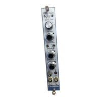
Describes the front panel controls and connectors of the 2015A Amplifier/TSCA.
Describes the rear panel connectors of the 2015A Amplifier/TSCA.
Illustrates and describes the internal controls and jumper settings for the 2015A.
Familiarizes users with the operation and controls for best performance in a gamma spectroscopy system.
Details the initial setup steps, including jumper plug settings and connections.
Explains critical adjustments like pole/zero for optimal resolution and baseline recovery.
Discusses the impact of shaping time constants on resolution at varying count rates.
Identifies common issues like vibration, radio interference, and ground loops that affect resolution.
Details the setup procedure for the Single Channel Analyzer (SCA) mode.
Details the setup steps for the SCA operation using a pulser and oscilloscope.
Provides cable compatibility data and output pulse examples for RG-58 and RG-62 cables.
Provides guidance on cleaning the front panel of the unit.
Lists the necessary equipment for performing the performance checkout procedure.
Details how to measure and verify NIM power supply voltages.
Describes how to measure and verify the current draw of the unit.
Outlines the procedure for checking the amplifier's operational parameters.
Describes how to check the amplifier output signal shape and amplitude.
Guides the adjustment of the pole/zero control for optimal pulse tail return.
Details how to check the proportionality of output amplitude across coarse gain settings.
Verifies the unipolar pulse shape for different shaping time constants.
Describes the procedure for measuring the unit's noise contribution.
Explains how to test the integral nonlinearity of the amplifier over its dynamic range.
Outlines the setup for verifying the Single Channel Analyzer (SCA) functionality.
Describes how to check the SCA output pulse parameters and logic.
Measures the timing walk of the SCA output relative to changes in input amplitude.
Tests the external control capability of the Lower Level (E) discriminator.
Lists the usual positions for internal jumper plugs before replacing covers.
Outlines the signal flow through the amplifier and SCA sections.
Describes the signal path and amplification stages within the amplifier.
Details the circuitry of the Single Channel Analyzer (SCA).
Explains the configuration and operation of the gain amplifier stages.
Describes the differentiation network, pole/zero cancellation, and input polarity selection.
Details the gain control and overload protection features of amplifier K2.
Explains the complex pole integrator and active filter networks for shaping.
Describes the output amplifier stage and driver transistors.
Details the circuitry of the restorer, which monitors and maintains the output baseline.
Describes the characteristics and logic levels of the SCA OUTPUT signal.
Elaborates on the timing and logic of the SCA output generation.
Describes the DISC output signal, its modes, and characteristics.
Details the circuit for generating the Lower Level (E) discriminator reference voltage.
Explains how the WINDOW (ΔΕ) reference voltage is generated.
Describes the reference voltage generation for the fast discriminator.
Details the circuit for providing the +5 volt supply.
Lists essential test equipment and documentation for troubleshooting.
Provides systematic steps and considerations for diagnosing malfunctions.
Guides on ordering and replacing components, including necessary information.
Describes the input signal characteristics and connector type.
Details the characteristics of the AMP OUTPUT and SCA OUTPUT signals.
Describes the multi-function capability of the DISC connector and signal types.
Lists and describes the function of each front panel control.
Explains the function of jumper plugs for output impedance, DISC, LLD, and SCA mode.
Details key performance metrics like gain, drift, nonlinearity, and noise.
Details performance metrics for the SCA function, including timing and linearity.
Lists the types of signal and power connectors.
Specifies the DC voltage and current requirements for the unit.
Provides size, weight, and NIM module compatibility.
Lists operating temperature and humidity ranges.
| Brand | Canberra |
|---|---|
| Model | 2015A |
| Category | Measuring Instruments |
| Language | English |