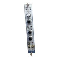
Model 2015A AMP/TSCA
■
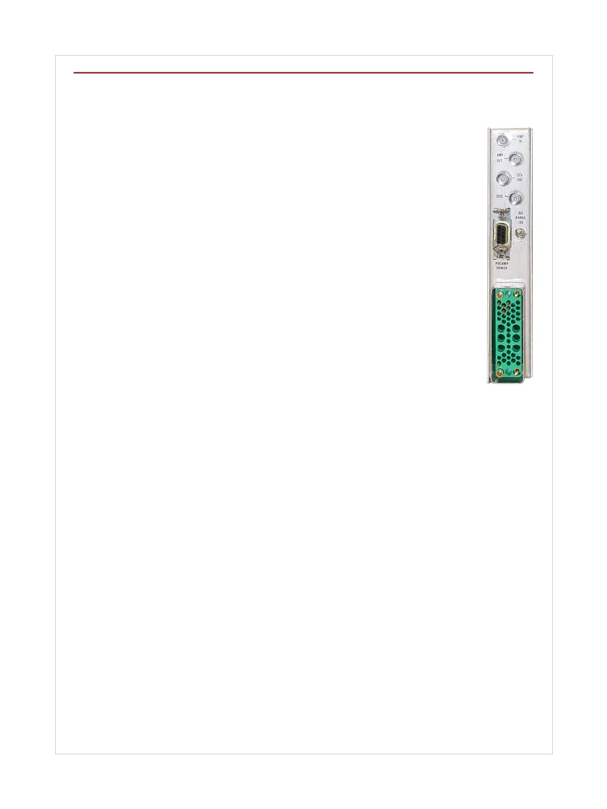
SCA OUTPUT – Provides a nominally 5 V (untermi-
nated) 500 ns positive pulse, delayed approximately
200 ns past the peak of the AMP OUTPUT signal; rise
time and fall time ≤25 ns; Z
out
≈ 50 Ω; BNC connectors
located on front and rear panels; short circuit protected;
output amplitude can be changed to 8 V by means of an
internal jumper.
INPUT/OUTPUT
■
DISC – Rear panel BNC connector having a multi-func-
tion capability; lower level (E) DISCriminator OUTPUT,
upper level (E + ∆E) DISCriminator OUTPUT, or LLD
SWEEP INPUT; one of these three modes is internally
selected with jumper plugs; shipped in E position.
When used as:
■
Lower Level (E) DISCriminator OUTPUT: Provides a
positive 5 V (unterminated), 500 ns pulse; rise time and
fall time ≤25 ns; Z
out
≈ 50 Ω; the LLD pulse is generated
when the positive edge of the AMP OUT signal crosses
the Lower Level (E) threshold setting; output amplitude
can be changed to +8 V by internal jumper.
■
Upper Level (E + ∆E) DISCriminator OUTPUT: Same
as lower level DISCriminator except the pulse appears
when the AMP OUT signal crosses the threshold set by
the sum of the LOWER LEVEL (E) and WINDOW (∆E)
controls.
■
LLD SWEEP INPUT: Accepts 0 to + 10 V input to exter-
nally control the SCA’s lower level discriminator; Z
in
≈
5.1 kΩ; dc coupled.
CONTROLS
■
COARSE GAIN – Rotary switch selects gain factors of
X4, X8, X16, X32, X64, X128.
■
FINE GAIN – Ten-turn precision locking dial potentiometer
selects variable gain factor of X3 to X10.
■
P/Z – Front panel multi-turn screwdriver pole/zero
adjustment optimizes the amplifier baseline recovery
and overload performance for the preamplifier fall time
constant and the main amplifier pulse shaping chosen;
30 µs to ∞ preamp fall time constant range.
■
INPUT – Toggle switch sets the Model 2015A for the
polarity of the incoming preamplifier signal.
■
TIME CONSTANTS – Internal pushbutton switch selects
SHAPING TIME constant of 0.5 µs or 2.0 µs; factory set
to 2.0 µs.
■
LOWER LEVEL (E) – Ten-turn locking dial precision
potentiometer selects a baseline from 0.1 V to 10 V for
the timing SCA mode, and 0 ±15 mV to 10 V for the
normal SCA mode.
■
WINDOW (∆E) – Ten-turn locking dial precision potenti-
ometer selects window width from 0 to 10 V or 0 to 1 V
depending on the position of the rear panel ∆E RANGE
switch.
■
∆E RANGE – Rear panel toggle switch selects the front
panel WINDOW (∆E) range as 0 to 10 V or 0 to 1 V, full
scale.
■
LED INDICATOR – Aids in setting the LLD just above
the system noise.
INTERNAL CONTROLS
■
Z
out
– Jumper plug selects AMP OUTPUT
impedance of ≤1 Ω or ≈ 93 Ω; factory set
to ≤1Ω.
■
DISC B – Jumper plug sets the rear panel
DISC BNC connector as an output or
input; factory set to OUT.
■
DISC A – Jumper plug sets the rear panel
DISC BNC connector to output the Lower
Level (E) Discriminator or the Upper
Level (E + ∆E) discriminator when DISC
B is in the OUT position; factory set to
ULD.
■
LLD – Jumper plug sets the LOWER
LEVEL discriminator threshold for INter-
nal or EXTernal; if EXTernal with DISC B
set to IN, the rear panel DISC BNC con-
nector can be used as the LLD SWEEP
input; factory set to IN.
■
SCA MODE – Jumper plug which allows
the SCA to operate in the TSCA or SCA
mode; factory set to TSCA.
PERFORMANCE
AMPLIFIER
■
GAIN – Continuously variable from X12
to X1280; product of COARSE and FINE
GAIN controls.
■
GAIN DRIFT – <±0.0075%/°C.
■
DC LEVEL DRIFT – <±50 µV/°C.
■
INTEGRAL NONLINEARITY – ≤±0.05% of full scale.
■
OVERLOAD RECOVERY – Recovers to ±2% of full
scale output in two pulse widths for a X1000 overload
with pole/zero cancellation properly set.
■
NOISE CONTRIBUTION – <7 µV referred to the INPUT
for gains ≥100X and 2 µs SHAPING.
■
PULSE SHAPING – Near-Gaussian shape; one dif-
ferentiator, two active integrators and only one second-
ary time constant; time to peak ≈ 1.75 X shaping time
constant.
■
RESTORER – Active, gated.
■
SPECTRUM BROADENING – FWHM of a
60
Co 1.33 MeV
gamma peak for an incoming count rate of 2 kcps to 50 kcps
and a 9 V pulse height will change less than 16%. These re-
sults may not be reproducible if associated detector exhibits
an inordinate amount of long rise time signals.
■
PEAK STABILITY – The peak position of a
60
Co 1.33 MeV
gamma peak for an incoming count rate of 2 kcps to 50 kcps
and a 9 V pulse height will shift less than 0.025%.