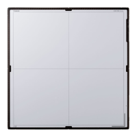
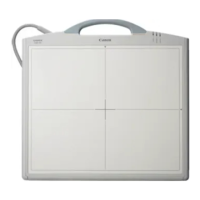
The Canon CXDI-40G COMPACT is a large-size sensor unit (430 mm × 430 mm) designed for easy installation into Bucky units, stands, or tables, including compatibility with Liebel-Flarsheim Bucky units without modification. This device functions similarly to the CXDI-40EG, featuring modifications to its reading circuit and supporting Ethernet connections for image data transfer.
Function Description:
The CXDI-40G COMPACT operates by converting X-ray images into photoelectric signals via its sensor unit. These scanned electrical signals then undergo A/D conversion, pass through a power box, and are transferred to a control PC over an Ethernet cable. The sensor unit comprises a LANMIT sensor, an AD board, a Di board, and a cover. After X-ray images are converted into visible light by a fluorescent screen, they are electrically stored in the sensor. The electrical signals are then read out, A/D converted, and temporarily stored in the frame memory. Simultaneously, reduced-size images are captured and transferred to the control PC via the Ethernet 100Base-TX interface. Upon completion of the reduced-size image capture, the full-size images in the frame memory are transferred.
The PWB-Di board, a key component, manages several functions:
- LANMIT-40E Drive: Drives the LANMIT-40E sensor through connected PCB-40EAD and PCB-D-EP boards.
- X-ray Exposure Synchronization: Communicates with the X-ray generator to synchronize LANMIT operation and X-ray exposure with image capture.
- Image Data Capture, Transfer, and Command Communication: Receives 14-bit/pixel, 2688 x 2688 pixel data from the PCB-40EAD boards after A/D conversion, storing it in SDRAM. It outputs captured image data via Ethernet (100Base-TX) to the control PC and communicates commands for PWB board or LANMIT operation modes through Ethernet.
- Temperature Detection: Thermal sensors on the PWB detect ambient temperature. A warning is displayed if the temperature reaches 48 °C (exposure remains enabled), and an error occurs if it reaches 49 °C or more (exposure is disabled).
- Serial Communication: Enables communication with an external general-purpose terminal via RS-232C for debugging.
- Ready Lamp Control: Manages the ready lamp unit.
- Log Recording: Records power-on time, number of exposures, exposure sequence, and other data in the flash ROM, accessible via serial communication over Ethernet.
- Sensor Information Storage: Stores unique sensor data (sensitivity, deficiencies) in the flash ROM, which can be read by an external device via Ethernet commands.
- Remote Updating: Allows firmware and HUB41 PLD codes to be updated from the control PC via Ethernet.
The power box serves as an interface and power supply unit, performing the following main functions:
- Power Supply: Supplies power to the sensor unit (internal power supply 7m unit).
- X-ray Generator Interfacing: Interfaces with the X-ray generator.
- Ethernet Communication Relay: Relays Ethernet communications while providing isolation from the network (AC 230V, basic insulation) for safety.
- Firmware Initialization Switches: Provides switches for starting the sensor unit firmware and initializing codes.
Important Technical Specifications:
- Effective Exposure Range: 430 x 430 mm
- Total Number of Pixels: 2706 x 2700 pixels
- Number of Effective Pixels: 7.2 million (2688 x 2688 pixels)
- Pixel Pitch: 160 µm x 160 µm
- Fluorescent Substance: GOS (LANMIT sensor)
- Sensor Sensitivity: Same as CXDI-40EG
- Exposure Time: 0 ms to 1 sec (normal mode), 1 to 3 sec (long-term mode)
- Output Gradations: 12 bits (4096 gradations), A/D 14 bits
- Transfer Method: Ethernet between sensor unit and PC (via power box)
- Preview Time: Approx. 3 sec
- Exposure Cycle Time: 15 sec (typical)
- External Dimensions (Sensor Unit): 470(W) × 548(L) × 32(H) mm (not including insulation sheet)
- External Dimensions (Power Box): 358(W) × 212(L) × 75(H) mm
- Color of Sensor Unit Exterior: Black (Cathodic electrodeposition coating)
- Mass (Sensor Unit): 11.0 kg (not including cables or ready lamp)
- Mass (Power Box): 4.2 kg
- Distance from Exterior CFRP Surface to Sensor Surface (Glass Surface): 6.6 ± 0.5 mm
- Patient Contact Surface: None
- Exterior Strength (Imaging Unit): Excess local weight: 12 kg (118 N) with 15 mm diameter for 1 minute (incoming X-ray surface only)
- Exterior Strength (Imaging Unit, Power Box): Excess local weight: 20 kg (196 N) with 15 mm diameter for 1 minute (locations other than incoming X-ray surface)
- Drop/Water-proofing/Resistance to Chemicals/IC X-ray Protection/Back-scattering Prevention: Not applicable/Not applicable/Not applicable/No protective lead/Not considered
- Grid: Fixed grid, not installable inside imaging unit, installed in Bucky unit/stand/table. Same specifications as 40EG grid.
- Phototimer: Not installable inside imaging unit, installed in Bucky unit/stand/table. Specifications identical to 40EG phototimer (except external dimensions).
- Calibration: Service staff only. Users can conduct self-diagnostic tests.
- Environmental Friendliness: RoHS supported.
- Compatible Control PC: FC-E21A for CXDI Control Station, or general-purpose PC with similar performance.
- Compatible Operating System: Windows XP SP3 (or SP2).
- Power ON/OFF Control: None.
- Stand: Dedicated stand, table, or universal stand.
- Connectability: Up to four units can be connected to a single control PC (using a hub). Up to three identical imaging units are possible. Imaging unit and power box are paired.
- X-ray Exposure Delay: Less than 0.3 sec.
- Exposure Preparation Time: Normal exposure mode: 10 sec; Long time exposure mode: 30 sec.
- Full Image Preview Time: Approx. 12 sec.
- Exposure Cycle Time: 15 sec or less in normal exposure mode.
- System Control Unit: Control PC, power box.
- Sensor DC/DC Power Supply: Inside power box.
- Sensor Cable: Overall length of 7 meters, one type.
- X-ray Monitor/Grid Detection/Remote Switch: None.
- Imaging Unit Status Display: External ready lamp.
- Temperature Sensor: Included (error when temperature exceeds 49°C).
- Power Consumption (one unit connected): Approx. (17) W (sleep mode/standby mode).
- Heat Generation: Approx. 35 kcal/h (15-sec exposure cycle time); Approx. 15 kcal/h (during sleep/standby).
- Environmental Conditions (Transportation & Storage): Temperature –30 to +60°C, Humidity 10% to 60% (no condensation), Atmospheric pressure 700 to 1060 hPa.
- Environmental Conditions (Operating): Temperature +10 to +35°C, Humidity 30% to 75% (no condensation), Atmospheric pressure 700 to 1060 hPa.
Usage Features:
The CXDI-40G COMPACT is designed for fixed installation in Bucky units, stands, or tables. It is not intended for portable use, installation in vehicles, or direct patient contact for imaging. The system supports both normal imaging (0-1000 msec) and long-term imaging (1001-3000 msec), with the maximum exposure time being 3 seconds. Preview display may be slower during long-term imaging or when using part buttons set for long-term imaging. Imaging preparation time is 10 seconds for normal imaging and 30 seconds for long-term imaging, during which the unit transitions from sleep to ready status.
Image processing involves several steps:
- Born image: Raw image from LANMIT before any correction. Distribution of these images is prohibited.
- Raw image: Born image after offset and gain correction, with LANMIT-specific characteristics corrected.
- Original image: Raw image after preprocessing.
- QA image: Original image after gradation processing, sharpening, and other processing performed by the CXDI.
- Diagnosis image: QA image after further user-processed enhancements for diagnostic purposes.
- Processing image: Diagnosis image after post-processing, either user-modified or default processed.
Maintenance Features:
- Service Training: Setup, repair, and maintenance must be performed by Canon-trained technicians, adhering to country-specific regulations.
- Cover Removal: Power must be off before removing external covers to prevent electric shock.
- Fuse Replacement: Fuses must be replaced with the specified type only after resolving the cause of failure.
- Grounding: The device must be properly grounded using the provided ground wire.
- Alternation Prohibition: No modifications to the medical device are allowed.
- Waste Control: Service providers are responsible for disposing of used parts and packing materials, while customers are responsible for disposing of the medical device, following local regulations for industrial waste.
- Installation Restrictions: Maintain specific distances from imaging unit sides and other locations. Cables should not be used with moving parts (except sensor and ready lamp cables) and must be routed to avoid excessive loads. Static charges must be discharged before handling PCBs and connectors.
- Calibration Imaging: Only service staff can perform calibration imaging. It should not be performed with the grid installed.
- Cable Bending Radius: For stationary parts, the inner cable circumference bending radius should be ≥ 25 mm; for moving parts, ≥ 50 mm. Cables must not be forcibly bent, folded, or pulled.
- System Installation Procedure: A detailed procedure covers unpacking, affixing insulation sheets, installing the imaging unit, connecting to the power box and control PC, adjusting alignment, installing the phototimer, starting/shutting down the system, X-ray controller interface, network settings, photo timer adjustment, fixed ROI area settings, firmware/PLD code installation, sensor serial number checks, startup menu setup, image quality checks, and post-installation checks.
- Backup and Recovery: The system supports backup methods using floppy disks and hard drives for critical setting data and system recovery in case of software file damage or hard drive crashes.
- Tool Modes: Special tool modes are available for launching the CXDI application on the control PC for maintenance purposes, though not for the CXDI-40G COMPACT imaging unit itself.
- Grid Installation Angle: The relative angular misalignment between the imaging unit sensor glass plate and the grid must be ± 1.0° or less. A dedicated tool (
audit_grid.exe) is used to check this angle.