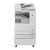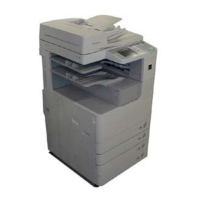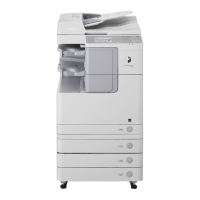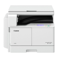
Do you have a question about the Canon imageRUNNER 2525 Series and is the answer not in the manual?
| Print Speed | 25 ppm |
|---|---|
| Print Resolution | 1200 x 1200 dpi |
| Copy Resolution | 600 x 600 dpi |
| Scan Resolution | 600 x 600 dpi |
| Duplex Printing | Yes |
| Monthly Duty Cycle | Up to 50, 000 pages |
| First-Copy-Out Time | 5.4 seconds |
| Warm-Up Time | 30 seconds or less |
| Maximum Original Size | 11 x 17 inches |
| Duplexing | Automatic |
| Operating System Compatibility | Windows, Mac OS, Linux |
| Connectivity | USB 2.0, Ethernet |
| Type | Laser |
| Functions | Print, Copy, Scan |
| Operation Panel | 5.7-inch LCD touch screen |
| Memory | 512 MB |
| Hard Disk Drive | Optionally available |
| Acceptable Originals | Book |
| Paper Weights | 64 to 128 g/m2 |
| Print Drivers | PCL6, UFR II, PostScript 3 |
| Power Consumption | Approx. 1.5 kW |
| Fax Transmission Speed | 33.6 Kbps |
Explains the safety classification of the machine as a Class 1 laser product and precautions for laser beam exposure.
Details safety precautions for power supply usage, including warnings against extension cords and socket-outlet accessibility.
Covers essential safety information about toner, including its non-toxic nature and a caution against throwing it into fire.
Outlines critical procedures and precautions to follow during assembly and disassembly to avoid hazards and ensure proper function.
Details the specifications, controls, and functions of the original exposure system, including major components and their roles.
Explains the functional configuration of the controller system, detailing the main controller PCB and its components.
Covers the specifications, controls, and configuration of the laser exposure system, including laser light, scanner motor, and polygon mirror.
Details the specifications, major components, and processes of the image formation system, including drum, charging, developing, and transfer.
Introduces the on-demand fixing method and provides specifications, major parts configuration, and temperature control details.
Outlines the specifications of the pickup and feed system, covering paper storage, pickup methods, paper size, and duplexing.
Provides an overview of all external and internal covers, listing them with corresponding reference pages for removal.
Details procedures for adjusting basic image position, including margins and non-image areas, with service mode settings.
Provides action steps required after replacing specific parts like CIS Unit, Platen Glass, ADF Scan Glass, Main Controller, and DC Controller.
Lists essential initial checks for site environment, paper, parts, and each unit/function system to identify potential issues.
Details common image failures and operational issues, providing occurrence areas, causes, and remedies for each.
Provides a detailed list of error codes, their descriptions, causes, and recommended remedies for troubleshooting.
Lists jam codes, their types, sensor names, and sensor IDs, categorized by main unit and cassette model.
Details alarm codes, including their titles, movement, causes, and measures for resolution, categorized by alarm type.
Details the SSSW (Service Soft Switch) functions, including composition, bit settings, and discussions of specific bits.
Outlines the test mode execution, covering D-RAM test, PG output, MODEM test, and FUNCTION test procedures.
Details essential checks for the installation site, power supply, environment, and required space before installing the equipment.
