
M
Mark JohnsonAug 17, 2025
What to do if my Canon Printer has a paper jam?
- JJacob HodgeAug 17, 2025
If your Canon Printer indicates a paper jam, remove the jammed paper. Afterward, press the Resume/Cancel button to attempt to clear the error.
What to do if my Canon Printer has a paper jam?
If your Canon Printer indicates a paper jam, remove the jammed paper. Afterward, press the Resume/Cancel button to attempt to clear the error.
What to do if Canon iP2700 says ink cartridge not properly installed?
If your Canon Printer displays an error indicating the ink cartridge is not properly installed, re-set the ink cartridge correctly. If the error persists, the ink cartridge may be defective, and you should replace it.
What to do if Canon iP2700 Printer says ink cartridge not installed?
If your Canon Printer displays a message indicating that no ink cartridge is installed, install the ink cartridge. If the error is not cleared after installation, the ink cartridge may be defective and require replacement.
What to do if Canon iP2700 Printer displays ink cartridge hardware error?
If your Canon Printer shows an ink cartridge hardware error, re-set the ink cartridge. If the error continues, the ink cartridge may be defective, and you might need to replace it.
What to do if Canon Printer says non-supported ink cartridge installed?
If your Canon Printer indicates that a non-supported ink cartridge is installed, install the supported ink cartridge. If the error persists, the ink cartridge may be defective, and you might need to replace it.
What to do if Canon Printer says ink cartridge in a wrong position?
If your Canon Printer indicates that the ink cartridge is in a wrong position, install the ink cartridge(s) in the correct position. If the error is not cleared, the ink cartridge may be defective. In that case, replace the ink cartridge.
What to do if Canon Printer says multiple ink cartridges of the same color installed?
If your Canon Printer displays a message indicating multiple ink cartridges of the same color are installed, replace the incorrect ink cartridge(s) with the correct one(s). If the error persists, the ink cartridge may be defective, and you may need to replace it.
What to do if Canon iP2700 Printer says the remaining ink amount unknown?
If your Canon Printer displays a message that the remaining ink amount is unknown, replace the ink cartridge with a new one. Printing without replacing the ink cartridge can damage the printer. However, to continue printing without replacing the ink cartridge(s), press the Resume/Cancel button for 5 sec. or longer to disable the function to detect the remaining ink amount.
What to do if Canon iP2700 Printer displays ink cartridge temperature sensor error?
If your Canon Printer displays an error indicating an ink cartridge temperature sensor issue, re-set the ink cartridge. If the error persists, the ink cartridge may be defective, and replacement may be necessary.
Why does my Canon iP2700 say ink cartridge not recognized (region code error)?
If your Canon Printer displays an error that the ink cartridge is not recognized due to a region code error, install the supported ink cartridge. If the error is not cleared, the ink cartridge may be defective, and you might need to replace the ink cartridge. This is because a non-supported ink cartridge (whose region code differs from the printer's region code) is installed.
Details operator call errors indicated by the orange alarm lamp and Status Monitor messages.
Details service call errors identified by blinking alarm and power lamps, including error codes.
Procedures for entering and using the printer's service mode via the Service Tool software.
Describes functions accessible through the printer driver's Maintenance tab for user-level operations.
Covers critical adjustments for carriage rail, chassis, and AC adapter replacement procedures.
Illustrates specific locations and recommended amounts of grease for printer maintenance.
Exploded view of main external printer components and internal logic boards.
Exploded diagram showing the first set of parts for the printer's print unit.
Exploded diagram showing the second set of parts for the printer's print unit.
Comprehensive list of all printer parts, including part numbers, descriptions, and remarks.
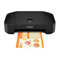
This document outlines the simplified service manual for the Canon iP2700, iP2770, and iP2780 series printers, providing essential information for troubleshooting, adjustment, settings, and parts replacement. It serves as a comprehensive guide for technicians and users to maintain and repair the device effectively.
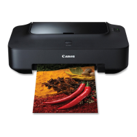
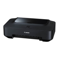
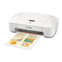
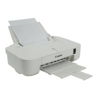
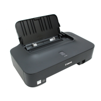
The Canon iP2700/iP2770/iP2780 series are inkjet printers designed for various printing tasks. The core functionality revolves around delivering high-quality prints, supported by a system that monitors and manages ink levels, paper handling, and print head operations. The printer utilizes ink cartridges (both color and black) to produce images and text.
Key functional components include:
The printer offers several features accessible through both user mode and service mode, catering to different levels of interaction.
User Mode Features: These functions are typically accessed via the printer driver's Maintenance tab on a connected computer, allowing users to perform routine maintenance and checks.
Error Display and Troubleshooting: The printer communicates errors and warnings through the Alarm lamp (orange) and Power lamp (green), as well as messages on the printer driver Status Monitor.
The service manual emphasizes several maintenance procedures, particularly those performed in Service Mode using a dedicated Service Tool, and specific physical adjustments and replacements.
Service Mode Features: Accessed by a specific button sequence during printer startup, the Service Mode allows technicians to perform advanced diagnostics, adjustments, and resets.
Physical Maintenance and Replacement:
This comprehensive approach to maintenance ensures the Canon iP2700/iP2770/iP2780 printers can be effectively serviced, prolonging their operational life and maintaining print quality.
| Print Technology | Inkjet |
|---|---|
| Max Print Resolution | 4800 x 1200 dpi |
| Max Resolution (Black) | 600 x 600 dpi |
| Print Speed (Black) | 7.0 ipm |
| Print Speed (Color) | 4.8 ipm |
| Connectivity | USB 2.0 |
| Input Tray Capacity | 100 sheets |
| Weight | 3.4 kg |
| Paper Sizes | A4, Letter, Legal, A5, B5, Envelopes |
| Operating Systems | Windows |