Do you have a question about the Canon iR2420 series and is the answer not in the manual?
| Print Technology | Laser |
|---|---|
| Paper Output | 100 sheets |
| Duplex Printing | Manual |
| Functions | Print, Copy, Scan |
| Print Resolution | 600 x 600 dpi |
| Copy Resolution | 600 x 600 dpi |
| Zoom | 25-400% |
| Scan Resolution | 600 x 600 dpi |
| Paper Capacity | 250 sheets |
| Paper Input (Standard) | 250 sheets |
| Paper Sizes | A4, A5, B5, Legal, Letter, Executive |
| Connectivity | USB 2.0 |
| Operating System Compatibility | Windows, Mac, Linux |
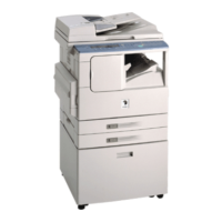
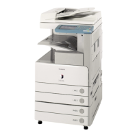
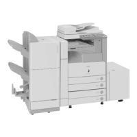
Details on the configuration of pickup, delivery, and original handling accessories for various machine models.
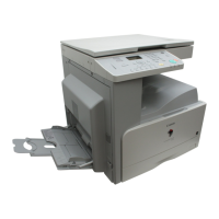
Overview of product specifications including names of parts, external views, and cross-sections.
Guidelines for user maintenance tasks, including cleaning procedures for various components.
Important safety information regarding laser light, CDRH regulations, toner handling, and fire prevention.
Essential checks before installation, including site selection and environmental requirements.
Procedures for unpacking the machine and installing key components like the drum unit and toner bottle.
Explanation of image processing flow, including reader entry and printer output stages.
Explanation of the CIS structure and analog control performed by the sensor.
Details on controlling laser activation timing, intensity, and scanner motor operations.
Explanation of how voltages are applied to charging and developing components for image density control.
Classification and causes of various jam types encountered in the pickup/feeding system.
Specifications, control mechanisms, and major components of the fixing system.
Control of fixing film speed and temperature, including target temperatures for different modes.
Details on the power supply system, including outlines and rated outputs for different configurations.
Step-by-step guides for removing various external covers and internal assemblies.
Procedure for inter-channel output correction after replacing the Contact Image Sensor (CIS).
Operations after replacing the Image Processor PCB, including firmware download and adjustments.
Comprehensive checklist for initial checks of the site environment, paper, units, and systems.
A table listing all error codes with their corresponding detail codes and explanations.
Detailed explanation of error codes, including main causes/symptoms and countermeasures.
Lists jam codes related to the printer unit, finisher, ADF, duplex unit, and inner 2-way tray.
Details on error codes specific to the finisher unit, including communication and sensor failures.
General information about the service mode, its functions, and how to use it.
Procedures for adjusting CIS position, reading position, and print position for optimal output.
Detailed procedure for downloading system software using the User Support Tool (UST).
List of special tools required for servicing the machine, including digital multimeter and test charts.