Chapter 7
7-25
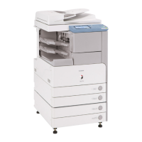
F-7-112
7.12.4.8 Removing the Pre-Exposure Lamp
0007-8391
iR2270 / iR2870 / iR3570 / iR4570 / / iR2270N / / iR2870N / / iR3570N /
/ iR4570N / iR2230 / / / iR3530 /
1) Open the 2 wire saddles [1], and disconnect the 2 relay connectors [2].
F-7-113
2) While freeing the lock [1] toward the right, detach the pre-exposure lamp
[2].
F-7-114
F-7-115
7.12.4.9 Removing the Left Cover
0007-8392
iR2270 / iR2870 / iR3570 / iR4570 / / iR2270N / / iR2870N / / iR3570N /
/ iR4570N / iR2230 / / / iR3530 /
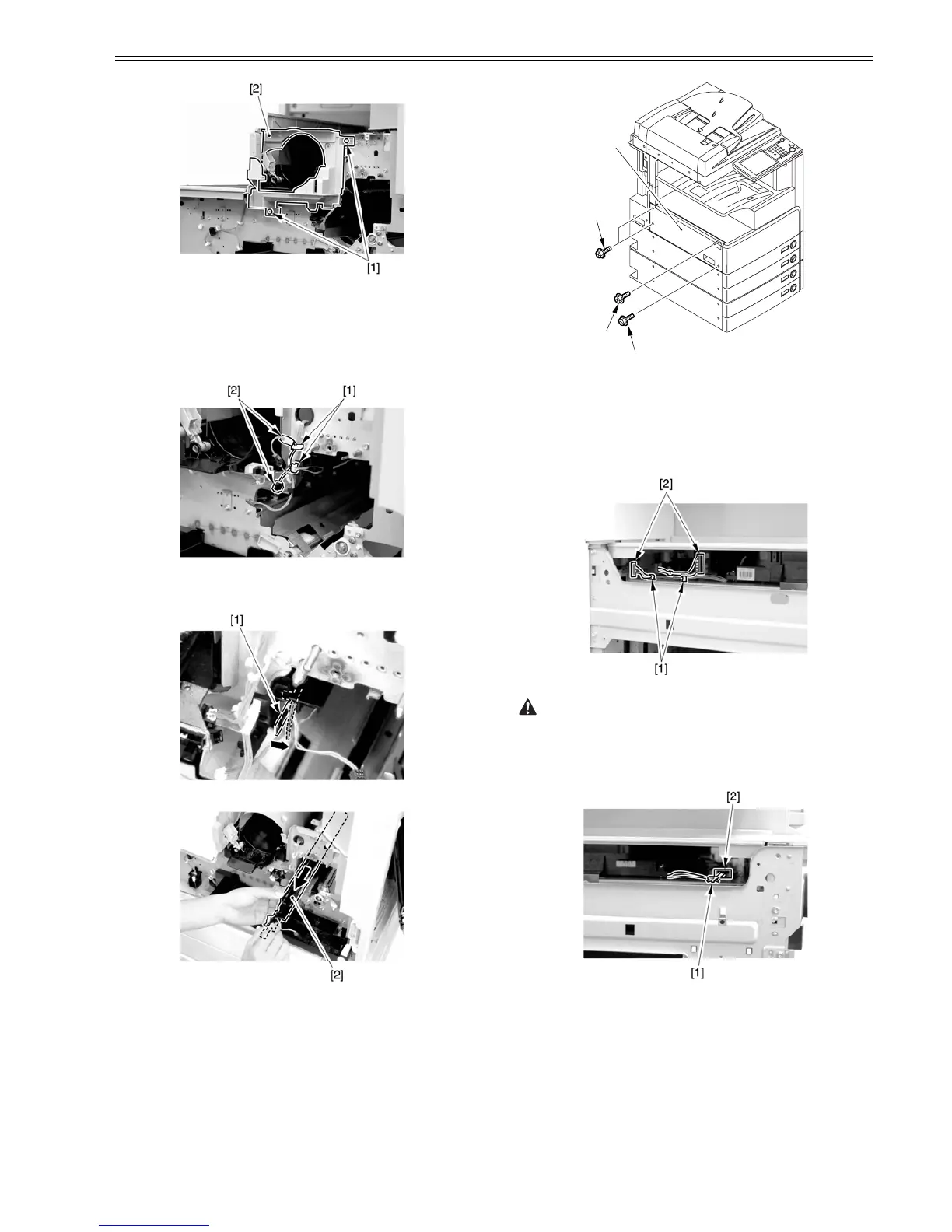
1) Remove the 4 screws [1], and detach the left cover [2].
F-7-116
7.12.4.10 Removing the Laser Unit
0007-8393
iR2270 / iR2870 / iR3570 / iR4570 / / iR2270N / / iR2870N / / iR3570N /
/ iR4570N / iR2230 / / / iR3530 /
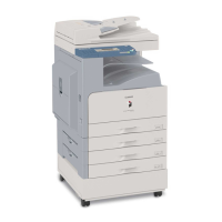
1) Open the 2 wire saddles [1], and disconnect the 2 connectors [2].
F-7-117
When you have disconnected the connector [1], be sure to take care so that
it will not come into contact with the PCB that is mounted to the laser scanner
unit. (The PCB is equipped with a laser intensity adjustment variable resis-
tor. Contact with the PCB can change the adjustment setting.)
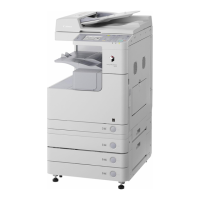
2) Open the wire saddle [1], and disconnect the connector [2].
F-7-118
3) Remove the screw [1], and detach the fixing [2].
[1]
[1]
[1]
[2]