Do you have a question about the Canon iR2018 Series and is the answer not in the manual?
Explains documentation symbols used to indicate special information, such as notes, cautions, or warnings.
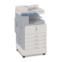
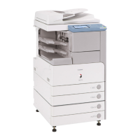
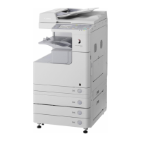
Details system configurations of pickup/delivery and original handling accessories for various models.
Lists and describes the technical specifications of the machine.
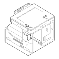
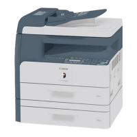
Identifies and labels the main external parts of the machine with diagrams.
Provides instructions on operating the machine, including power on/off procedures.
Identifies and describes the functions of the machine's control panel components.
Lists and explains various settings configurable in the user mode.
Outlines essential maintenance tasks that users can perform.
Provides crucial safety information for operating the machine.
Details the technical specifications of the machine.
Lists the available functions of the machine.
Lists supported paper types and their specifications.
Steps to perform before starting the installation.
Procedures for unpacking and installing the machine.
Detailed instructions for installing the drum unit.
Step-by-step guide for installing the toner bottle.
Instructions for setting up the paper cassettes.
Procedure to check the quality of printed images after installation.
Steps to set the country/region for proper machine operation.
Instructions for setting the machine's date and time.
Steps to verify the network connection status.
Detailed instructions for installing the card reader.
Procedure for registering card IDs after installation.
Instructions for installing the heater PCB.
Instructions for installing the reader heater.
Step-by-step guide for installing the reader heater harness.
Instructions for installing the cassette heater.
Instructions for installing the control card cable.
Describes the construction and mechanisms of the main controller.
Details the construction and major control mechanisms of the Image Processor PCB.
Provides an overview of the image processing flow within the machine.
Describes the modules involved in image processing.
Explains how image data from the reader unit is processed.
Illustrates the data flow for various functions.
Instructions for replacing main controller parts.
Detailed procedure for removing and replacing the main controller PCB.
Procedure for replacing the SDRAM module.
Describes the construction of the original exposure system.
Describes basic operational sequences.
Details various control mechanisms for the original exposure system.
Explains the function and operation of the contact image sensor.
How the machine detects the size of the original document.
How the machine controls dirt detection to improve image quality.
Details the image processing system.
Instructions for replacing parts related to the original exposure system.
Procedure for replacing the copyboard glass.
Procedure for replacing the reader controller PCB.
Procedure for replacing the contact image sensor.
Procedure for replacing the original size sensor.
Procedure for replacing the reader heater.
Describes the construction of the laser exposure system.
How laser activation timing is controlled.
How laser light intensity is controlled.
How the laser scanner motor speed is controlled.
How the laser shutter is controlled.
Procedure for replacing the laser scanner unit.
Lists specifications of the image formation system.
Details the step-by-step image formation process.
How the high-voltage system is driven and controlled.
Details the drum unit and its components.
Explains the charging mechanism.
Overview of the developing unit.
Details the control of developing bias.
Explains the toner container structure and function.
Details the transfer unit.
How transfer bias is controlled.
Explains the separation mechanism.
Procedures for cleaning the photosensitive drum.
How the machine detects when the waste toner box is full.
Instructions for replacing machine parts.
Procedure for replacing the drum unit.
Procedure for replacing the developing assembly.
Procedure for replacing the transfer charging roller.
Describes the construction of the pickup/feeding system.
Shows the locations of main units in the pickup/feeding system.
Illustrates the layout of rollers in the pickup/feeding system.
Diagrams showing the paper path for various configurations.
Shows the layout of sensors in the pickup/feeding system.
Information on detecting paper jams.
Details the cassette pickup unit.
Details the manual feed pickup unit.
Instructions for replacing parts in the pickup/feeding system.
Procedure for replacing the pickup roller.
Procedure for replacing the cassette unit.
Procedure for replacing the cassette pickup assembly.
Procedure for replacing the cassette size sensor.
Procedure for replacing the cassette retry paper sensor.
Procedure for replacing the cassette paper sensor.
Procedure for replacing the cassette pickup solenoid.
Procedure for replacing the manual pickup roller.
Procedure for replacing the manual feed tray paper sensor.
Procedure for replacing the manual feed pickup solenoid.
Procedure for replacing the registration roller.
Procedure for replacing the registration clutch.
Procedure for replacing the separation roller.
Procedure for replacing the separation pad.
Describes the construction of the fixing system.
How the fixing film speed is controlled.
How the fixing film temperature is controlled.
How the machine detects paper passage through the fixing unit.
Explains the machine's protective functions for the fixing heater.
Instructions for replacing parts in the fixing system.
Procedure for replacing the fixing unit.
Procedure for replacing the pressure roller.
Procedure for replacing the fixing film unit.
Procedure for replacing the fixing delivery sensor.
Procedure for replacing the fixing film sensor.
Overview of the machine's control panel.
Information about the machine's fans and their control.
Overview of the machine's power supply system.
Details the protection functions of the power supply.
Instructions for replacing machine parts.
Procedures for removing external covers.
Procedure for replacing the main drive assembly.
Procedure for replacing the fixing drive assembly.
Procedure for replacing the power supply unit.
Procedure for replacing the control panel.
Procedure for replacing the DC controller PCB.
Procedure for replacing the option power supply PCB.
Procedure for replacing the HVT PCB.
Procedure for replacing the fixing heat discharge fan.
Procedure for removing the fan filter.
Procedure for replacing the main drive motor.
Procedure for replacing the fixing driver motor.
Procedure for removing the left door.
Details the Remote Device Services (e-RDS) system.
Procedure for testing device connection to UGW.
Procedure to reset e-RDS settings to factory defaults.
Steps for network connection settings during installation/maintenance.
Procedures for setting up e-RDS during installation/maintenance.
Guidance for troubleshooting common issues.
Lists and explains error messages.
Identifies parts that require periodic replacement.
Lists parts that may require replacement due to wear.
Details the scheduled servicing procedure.
Procedures related to the scanning system adjustments.
Procedures related to the image formation system adjustments.
Information on procedures for electrical components.
Steps for backing up user data before clearing.
Initial checks to perform before troubleshooting image faults.
Lists and describes electrical components.
Lists and describes clutches and solenoids.
Lists and describes the motors.
Lists and describes the fans.
Lists and describes the sensors.
Lists and describes the switches.
Lists lamps, heaters, and other components.
Lists PCBs used in the machine.
A table listing all error codes with details and countermeasures.
Detailed explanations and countermeasures for specific error codes.
Lists jam codes for different parts of the machine.
Lists error codes specific to the finisher.
Lists error codes related to FAX functions.
General overview of the service mode functions.
How to navigate and use the service mode on touch panel models.
Lists the menus available within the service mode.
Setting of bit switches within service mode.
Settings for printer functions.
Settings for numeric parameters.
Settings for scanner functions.
Network parameter settings.
Settings for system functions.
How to display counter information.
Information on generating service reports.
Lists recorded errors and their history.
Procedure for downloading system software.
Procedure for initializing set values.
How service error codes are displayed.
Information on using the test mode.
Overview of the system software upgrade process.
Overview of the Service Support Tool.
Steps to prepare for software upgrading.
Procedures for downloading system software.
Procedure for downloading RUI and language files.
Procedure for downloading boot software.
Alternative methods for upgrading the system.
Procedure for downloading PCL software.
Procedure for downloading the CA certificate.
Lists service tools required for maintenance.
Details special tools needed for servicing.
Lists oils and solvents used for maintenance.
| Duplex Printing | Manual |
|---|---|
| Copy Resolution | 600 x 600 dpi |
| Type | Monochrome Laser Multifunctional |
| Print Speed | 18 ppm |
| Print Resolution | 600 x 600 dpi |
| Paper Capacity | 250 sheets |
| Paper Output | 100 sheets |
| Paper Sizes | A4, A5, B5, Legal, Letter, Executive |
| Copy Speed | 18 cpm |
| Multiple Copy | Up to 99 copies |
| Scan Resolution | 600 x 600 dpi |
| Scan to | USB |
| Interface | USB 2.0 |
| Supported OS | Windows, Mac |
| Warm-up Time | Less than 15 seconds |