5
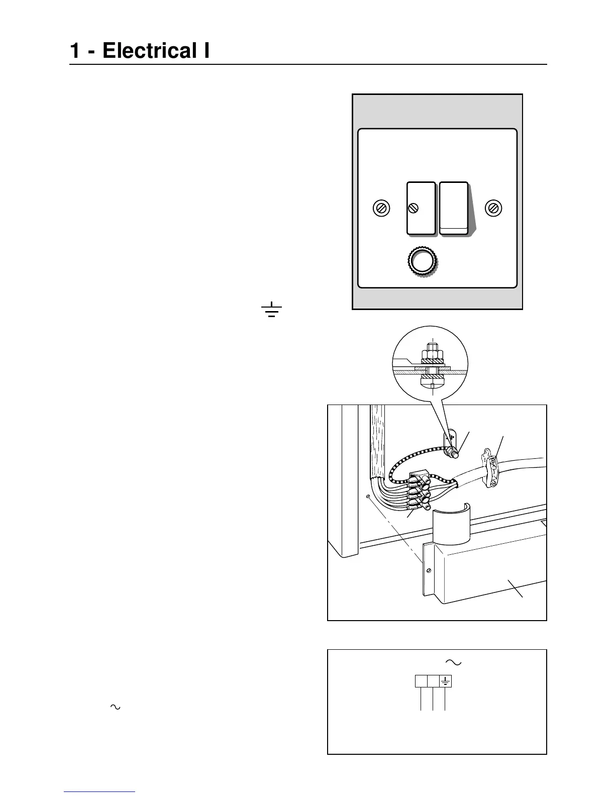
This appliance must be connected to a
double pole isolating switch (fig. 1.1) and
to the terminal block in the cooker (figs.
1.2 & 1.3) using the following guide:
Fig. 1.1
1) The wire which is coloured brown
must be connected to the terminal
marked L (Live), or coloured Red.
2) The wire which is coloured blue
must be connected to the terminal
marked N (Neutral), or coloured
Black.
3) The wire which is coloured green
and yellow must be connected to
the terminal marked E (Earth)
or coloured Green.
IMPORTANT: These connections must
be carried out by a qualified electrical
engineer.
CONNECTING FEEDER CABLE
To connect the feeder cable to the cook-
er it is necessary to:
– Remove the screw that hold shield “A”
behind the cooker (fig. 1.2).
– Insert the feeder cable of the suitable
section (as described in the next chap-
ter) into the cable clamp “D”.
– Connect the phase and earth cables to
the terminal block “B” according to the
diagram in figure 1.3.
– Pull the feeder cable and block it with
cable clamp “D”.
– Re-mount shield “A”.
Fig. 1.2
D
B
A