CAREFREE OF COLORADO INSTALLATION MANUAL TRAVEL'R DIRECT RESPONSE
052567-001r5 3
I
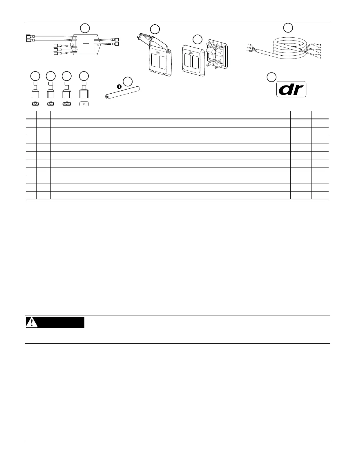
TEM DESCRIPTION QTY NOTE
1
Sensor Module 1
2
Switch Kit 1
3
Covered Bezel, 2 Switch 1 1
4
Cable 205" 1
5
Terminal, Female, .187 18-22 awg 3
6
Terminal, Female, .187 14-16 awg 2
7
Terminal, Female, .25 14-16 awg 3
8
Terminal, Male, .25 14-16 awg 3
9
Cord Retainer 1
10
Label, Direct Response 1
Note: 1. The covered bezel (item 3) is optional and ordered separately. Refer to page 7 for information about
NFPA 1192 RV Standard, Section 6.4.9 (Switch Installation Requirements).
PRIOR TO INSTALLING THE KIT
For New Installations – These instructions assume that the awning and arms have been mounted and that the
motor cable from the arm has been routed through the exterior wall as described in the awning installation
instructions. These instructions replace the switch and wiring directions included with the awning.
For Existing Installations – The installer must locate and remove any existing switches. Access to the motor cable
and the 12VDC/Ground wires is required.
1. Determine the location of the switches:
1.1 Do not mount the switches near heat producing elements such as LP appliances or engine
exhaust components.
1.2 The dimensions for the switch plate are shown on page 7.
WARNING TO AVOID SHOCK HAZARD AND/OR ACCIDENTAL SYSTEM SHORTING, ALWAYS DISCONNECT
THE VEHICLE BATTERY AND ELECTRICAL SOURCES BEFORE WORKING WITH ELECTRICAL WIRING AND
COMPONENTS.
When the Direct Response installation is complete return to the original awning instructions for any final
assembly required.
LCDR002
1
2
4
5 876
10
9
RETRAC
T
ON
E
X
TE
ND
OFF
Aw
ning C
o
n
trol
RETRACT
O
N
E
X
TEN
D
Awn
ing
Co
n
tr
o
l
OF
F
3