Caratteristiche meccaniche
protezione: IP20
dimensioni: 87x36x60 mm (2 moduli DIN)
montaggio: a guida DIN
sezione minima cavi di collegamento: 0,75 mm
2
sezione massima cavi di collegamento: 2,5 mm
2
distanza massima collegamenti agli ingressi: 3 m
temperatura e umidità di immagazzinamento:
-10T70°C - 90% U.R.
temperatura e umidità di esercizio: 0T50°C - 90% U.R.
inquinamento ambientale: normale
limiti di temperaturasuperfici: come temperatura di esercizio
isolamento: rinforzato
tipo di contatti: 1 c
Esempio di utilizzo combinato dei moduli
Si voglia gestire la regolazione di un sistema utilizzando
due set-point, uno per il controllo del riscaldamento e l’al-
tro per il controllo del raffreddamento mediante due valvo-
le modulanti con segnale 0/10 V. Qualora l’azione della
valvola di raffreddamento non riesca a frenare l’innalza-
mento della temperatura, il sistema dovrà attivare un cir-
cuito frigorifero ulteriore. Si richiede, inoltre, una segnala-
zione di allarme generale.
Soluzione: in questo caso sarà necessario impiegare la
versione per relè a stato solido a 4 uscite (versione IR32A
o IRDRA); la programmazione dello strumento potrà esse-
re eseguita utilizzando i parametri speciali partendo dal
Modo preprogrammato, C0=2.
Proponiamo lista dei parametri di configurazione da modi-
ficare (PW77): C12=0,2 C33=1
per OUT1: C34=2 C35=1 C36=50 C37=-50
per OUT2: C38=2 C39=0 C40=100 C41=-50
per OUT3: C42=1 C43=1 C44=-100 C45=100
per OUT4 : C46=3 inalterati gli altri
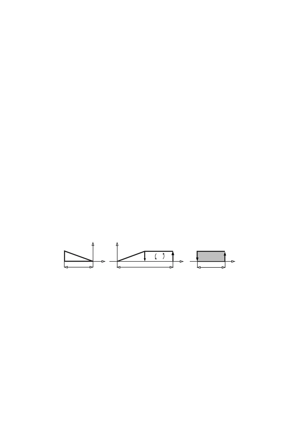
La logica di regolazione ottenuta è raffigurata in questo disegno.
Per il collegamento:
ci serviamo di due moduli CONVONOFF0 per la gestione
dell’uscita di allarme e del compressore, mentre due
moduli CONV0/10A0 gestiranno le uscite delle due rampe
analogiche.
Tutti i moduli (e l’IR) possono essere alimentati da un
unico trasformatore a 24 Vac. Si dovrà alimentare il modu-
lo COV0/10A0 e valvola con lo stesso trasformatore rispet-
tando la polarità di G0. In questo caso dal trasformatore il
G0 di alimentazione ai moduli dovrà corrispondere il G0
alla valvola (in alcuni casi si può chiamare L2 o N). Si
omette il collegamento del G0 in uscita del modulo con la
valvola, in quanto è il trasformatore a collegare il riferi-
mento del segnale analogico tramite appunto la connes-
sione G0. Al trasformatore la connessione a terra del
secondario può essere fatta al polo identificato G0.
Per il collegamento dei vari IR ai moduli basterà collegare
i “+“ e “-“ delle uscite dell’IR ai rispettivi Y+ e Y- dei
corrispondenti moduli.
Mechanical characteristics
protection index: IP20
dimensions: 87x36x60mm (2 DIN modules)
mounting: DIN rail
min. section of connection cables: 0.75mm
2
max. section of connection cables: 2.5mm
2
max. distance of connections to the intputs: 3m
storage temperature and humidity: -10T70°C - 90%rH
operating temperature and humidity: 0T50°C - 90%rH
environmental pollution: normal
extreme surface temperature conditions: as operating
temperature
insulation: reinforced
contact type: 1c
Practical examples: Using different modules
Control of a system with two set-points, one for heating,
the other for cooling through 2 modulating 0/10V valves.
Should the action of the valves be not sufficient to keep
the temperature within the set threshold, the system will
actuate a refrigerating circuit. The system should also be
equipped with a general alarm signal.
Solution: use a 4-output model (IR32A or IRDRA).
Program the instrument using the special parameters;
start from the factory-set C0=2.
Here is the list of the configuration parameters to be
modified (password 77): C12=0.2 C33=1
OUT1: C34=2 C35=1 C36=50 C37=-50
OUT2: C38=2 C39=0 C40=100 C41=-50
OUT3: C42=1 C43=1 C44=-100 C45=100
OUT4: C46=3 remaining parameters unchanged
The graph below shows the new control logic:
Connections:
Use two modules CONVONOFF0 to manage alarm and
compressor outputs. Other two CONV0/10A0 modules will
manage the analogue outputs.
All modules and the IR can be powered from the same
24Vac transformer.
Power the COV0/10A0 module and the valve from the
same transformer respecting the G0 polarity.
In this case the power supply G0 from transformer to
modules must correspond to the G0 to the valve (someti-
mes indicated with L2 or N).
Earth the secondary of the transformer at point identified
with G0.
To link up the various IR instuments to the modules, con-
nect the outputs' "+" and "-" to the dedicated Y+ and Y-
on the corresponding modules.
65
 Loading...


