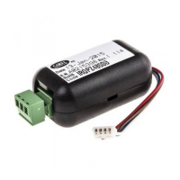
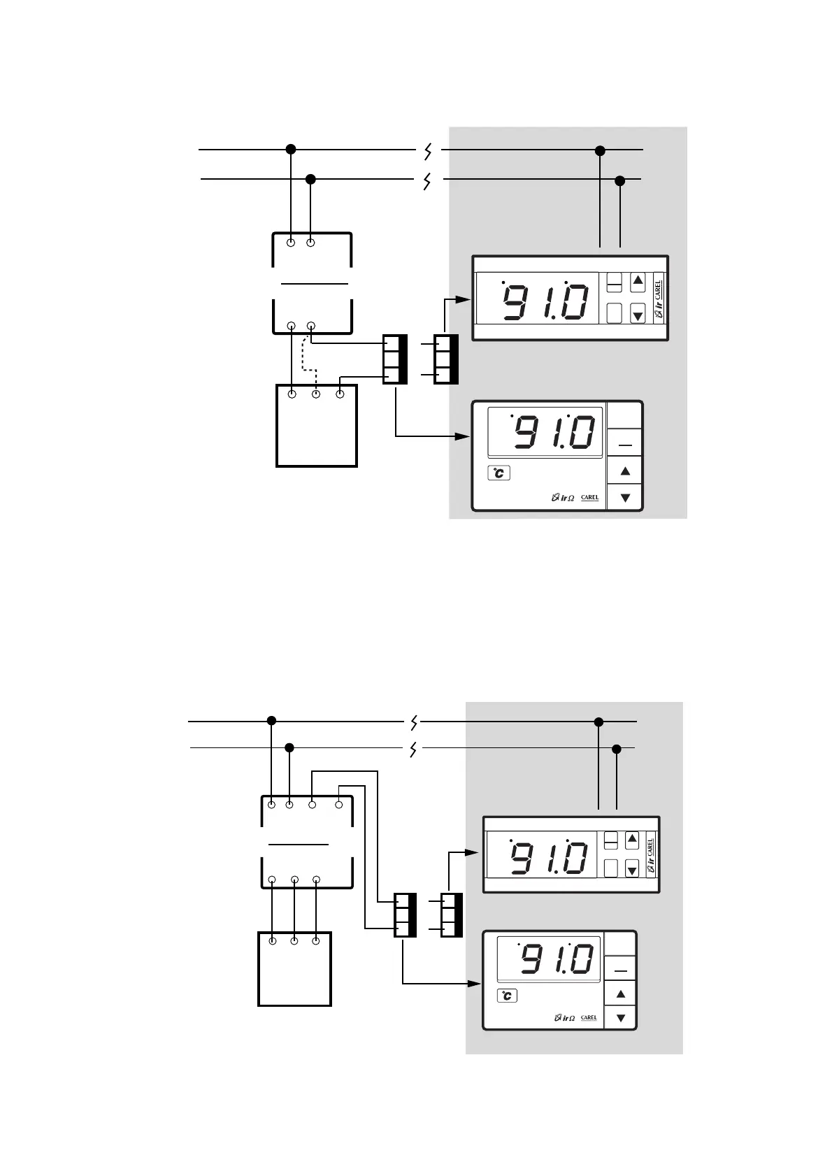
I diagrammi sottostanti rappresentano due tipici esempi
del collegamento della sezione alimentatore e alimentatore/
convertitore con una sonda esterna.
The figures below show two typical connections between
power supply and power supply/converter to an external
sensor.
67
reverse
direct
PRG
mute
SEL
PRG
mute
reverse
direct
SEL
Converter
module
G G0
Vcc
GND
Active
sensor
+ - out
Power Supply 24 V~
Main supply
Out
M
(*)
(*) per sonde a 3 fili
only 3-wire sensors
Lo schema è valido per sonde alimentabili a 24 Vdc, con segnali in tensione
(IR con ingresso -0,4/ 1Vdc ) e in corrente (IR con ingresso 0/20–4/20 mA ).
This diagram is effective for both dc voltage signal, with power supply 24Vdc
(IR
-0.4
/ 1Vdc input ) and current signal (IR - 0/20–4/20mA input ) sensors.
1
2
3
7
8
9
reverse
direct
PRG
mute
SEL
PRG
mute
reverse
direct
SEL
Converter
module
G G0
Vcc GND IN
Active
sensor
+ - out
Power Supply 24 V~
Main supply
out
GNDOUT
M
0/10Vdc signal
- 0.4/ 1Vdc input models
1
2
3
7
8
9
24 Vdc
Lo schema è valido per sonde 0/10 Vdc, 3 fili, alimentabili a 24 Vdc.
This diagram is effective for probes 0/10Vdc, 3 wires, with power supply 24Vdc.
 Loading...