13
-
+
-
+
Fig. 2. t
1 2 3 4
5 6 7 8
Y+ Y-G0
G
Input signal
G0 4-20mA
Signal output
G0 0-10Vdc
Signal output
CONV0/10A0
24 Vac
230 Vac
Y+
Y-
G0
G
Input signal
1 2
3 4
5 6 7 8
No
Output
Com
Nc
CONVONOFF0
Fig. 2. s
ENG
ir33 universale +030220801 - rel. 1.0 - 16.04.2008
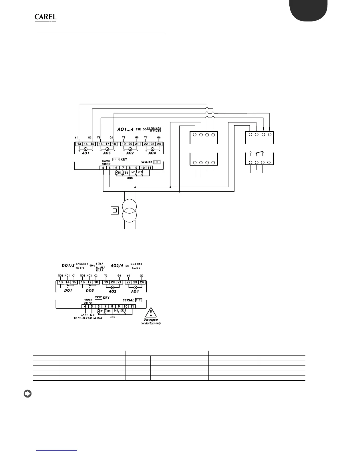
2.5 Connection diagrams
2.5.1 Connection to the CONV0/10A0 and
CONVONOFF0 modules (accessories)
The CONV0/10A0 and CONVONOFF0 modules convert a PWM output
for SSR to a 0 to 10 Vdc analogue output and ON/OFF relay output
respectively. Below is an example of an application that uses model
DN33A7LR20. Note that the same controller can thus have 3 di erent
types of outputs. If only the 0 to 10 Vdc analogue output and the relay
output are required, model DN33E7LR20 can be used; the wiring diagram
is shown below.
Key
CONV0/10A0 & CONVONOFF0 modules CONV0/10A0 module CONVONOFF0 module
Terminal Description Terminal Description Terminal Description
1 24 Vac power supply 5 0 to 10 Vdc output reference 5 Normally open
2 Power supply reference 6 0 to 10 Vdc output 6 Common
3 PWM control signal (+) 7 4 to 20 mA output reference 7 Normally closed
4 PWM control signal (-) 8 4 to 20 mA output 8 Not connected
The control signal to terminals 3 & 4 on the CONV0/10VA0 and CONVONOFF
modules is optically-isolated. This means that the power supply (G, G0)
can be in common with the power supply to the controller.
 Loading...