30
ENGLISH
µC
2
SE - +030220426 - rel. 2.0 - 03.08.2009
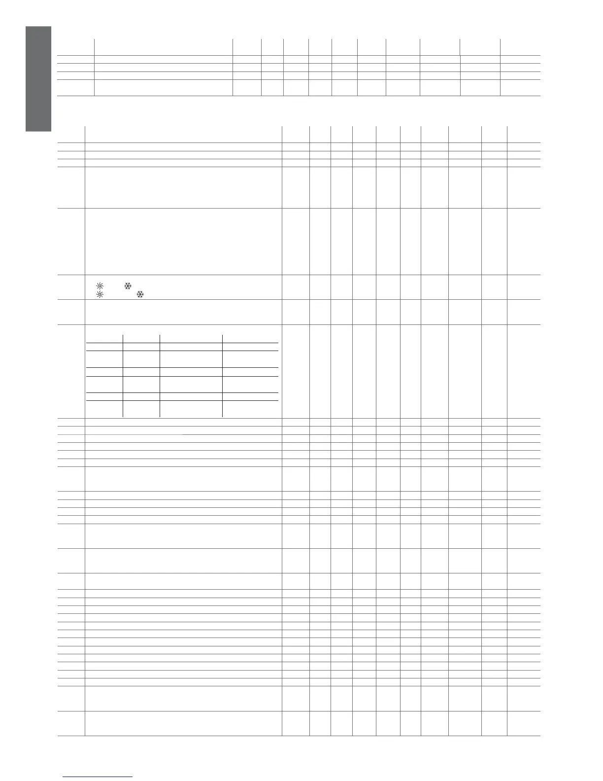
4.3.9 Firmware parameters (F-r*)
display
indicat.
parameter and description default
level
min. max. U.O.M. variat. default visibility supervis.
variable
Modbus variable type
H99 Software version, Driver 2 D 0 999 Int - 14 - 1 (R) 208 Integer
H98 Software version, Driver 1 D 0 999 Int - 0 X 2 (R) 209 Integer
H97 Expansion software version D 0 999 Int - 0 V 3 (R) 210 Integer
H96 Software version (displayed when powering up the
instrument)
D 0 999 Int - 0 XV 4 (R) 211 Integer
Table 4.i
4.3.10 Alarm setting parameters (P*)
display
indicat.
parameter and description default
level
min. max. U.O.M. variat. def. visibility supervis.
variable
Modbus variable
type
P01 Flow switch alarm delay when starting the pump U 0 150 s 1 20 - 63 (R/W) 270 Integer
P02 Flow switch alarm delay during steady operation U 0 120 s 1 5 - 64 (R/W) 271 Integer
P03 Low pressure alarm delay at compressor start-up U 0 200 s 1 40 - 65 (R/W) 272 Integer
P04 Enable compressor capacity-control with high pressure
0= capacity control deactivated
1= capacity-control with high pressure active
2= capacity-control with low pressure active
3= capacity-control with high and low pressure active
U 0 3 Flag 1 0 P 66 (R/W) 273 Integer
P05 Alarm reset
0= HP1-2/LP1-2/A1-2/Lt manual
1= HP1-2/LP1-2/A1-2/Lt automatic
2= HP1-2/A1-2/Lt manual LP1-2 automatic
3= HP1-2 manual LP1-2/A1-2/Lt automatic
4= HP1-2/LP1-2 manual A1-2/Lt automatic
5= HP1-2/LP1-2 (thrice per hour) manual A1-2/Lt automatic
6= HP1-2/LP1-2 (thrice per hour) manual; A1-2/Lt manual
F 0 6 Flag 1 0 - 67 (R/W) 274 Integer
P06 Cooling/heating logic
0=:
Chiller, : Heat pump
1=:
Heat pump, : Chiller
F 0 1 Flag 1 0 - 19 (R/W) 19 Digital
P07 Low pressure alarm with pressure probe
0= Disabled
1= Enabled
F 0 1 Flag 1 0 P 68 (R/W) 275 Integer
P08 Digital input 1 selection
0= N 1=FL man. 2=FL auto. 3=TP man.
4=TP auto 5= TC1 man. 6= TC1 auto. 7= TC2 man.
8= TC2 auto. 9= Cool/heat 10= Cool/heat with
delay
11= LA man.
12= LA auto. 13= 2° Set 14= 2° Set timer 15= stop defrost c.1
16= stop
defrost c.2
17= start
defrost c.1
18= start defrost c.2 19= step 1
20 = step 2 21= step 3 22= step 4 23= remote ON/OFF
24=Comp.
alarm1
25=Comp.
alarm2
26=Comp. alarm3 27=Comp. alarm4
F 0 23 Int 1 0 - 69 (R/W) 276 Integer
P09 Digital input 2 selection F 0 27 Int 1 0 - 70 (R/W) 277 Integer
P10 Digital input 6 selection F 0 27 Int 1 0 X 71 (R/W) 278 Integer
P11 Digital input 7 selection F 0 27 Int 1 0 X 72 (R/W) 279 Integer
P12 Digital input 10 selection F 0 27 Int 1 0 X 73 (R/W) 280 Integer
P13 Confi guration of B4 as P8 if /4=1 (digital input) F 0 27 Int 1 0 - 74 (R/W) 281 Integer
P14 Confi guration of B8 as /8=1 (digital input) F 0 27 Int 1 0 X 75 (R/W) 282 Integer
P15 Select low pressure alarm
0= not active with compressor OFF
1= active with compressor OFF
F 0 1 Flag 1 0 - 76 (R/W) 283 Integer
P16 High temperature alarm set U -400 1760 °C/°F 0.1 800 - 38 (R/W) 38 Analog
P17 High temperature alarm delay at start-up U 0 250 s 1 30 - 77 (R/W) 284 Integer
P18 High pressure alarm set from transducer F P33 999 Dbar 0.1 200 P 39 (R/W) 39 Analog
P19 System low temperature alarm set point U -400 1760 °C/°F 0.1 100 - 40 (R/W) 40 Analog
P20 Enable system start-up protection
0= Disabled
1= Enabled
U 0 1 Flag 1 0 - 20 (R/W) 20 Digital
P21 Alarm relay output logic
0= normally de-activated
1= normally activated
F 0 1 - 1 0 - 8 (R/W) 8 Digital
P22 Low pressure alarm delay at start-up
Compressor in heat pump
U 0 200 s 1 40 - 86 (R/W) 293 Integer
P23 Low pressure alarm delay at compressor start-up in defrost U 0 999 s 1 40 - 87 (R/W) 294 Integer
P24 Deactivate compressors with HP and LP capacity-control D 0 1 - 1 0 P 21 (R/W) 21 Digital
P25 Select digital output 2 F 0 17 Int 1 0 - 108 (R/W) 315 Integer
P26 Select digital output 3 F 0 17 Int 1 0 - 109 (R/W) 316 Integer
P27 Select digital output 4 F 0 17 Int 1 0 - 110 (R/W) 317 Integer
P28 Select digital output 5 F 0 17 Int 1 0 - 111 (R/W) 318 Integer
P29 Select digital output 7 F 0 17 Int 1 0 X 112 (R/W) 319 Integer
P30 Select digital output 8 F 0 17 Int 1 0 X 113 (R/W) 320 Integer
P31 Select digital output 9 F 0 17 Int 1 0 X 114 (R/W) 321 Integer
P32 Select digital output 10 F 0 17 Int 1 0 X 115 (R/W) 322 Integer
P33 Low pressure alarm threshold F 0 P18 Dbar 0.1 10 P 76 (R/W) 76 Analog
P34 Select digital input 5 F 0 23 Int 1 23 - 122 (R/W) 329 Integer
P35 Mute alarm with “mute“ button
0= no
1= yes
F 0 1 - 1 0 - 23 (R/W) 23 Digital
P36 Type of high pressure alarm management
0= always
1= only if compressor active and 2 s after activation
F 0 1 - 1 0 - 24 (R/W) 24 Digital
Table 4.i
 Loading...


