Do you have a question about the Carel µC2SE and is the answer not in the manual?
Guidelines for product installation, handling, and environment.
Information on proper disposal of CAREL products according to regulations.
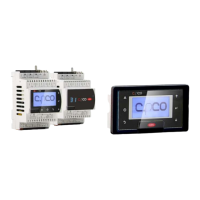
Overview of the µC2SE controller and its main functions.
Explanation of the µC2SE display and symbols.
Step-by-step guide for programming and saving parameters.
Description of the µC2SE keypad and its usage.
Illustrates the general connection diagram for the µC2SE.
Shows different network layout configurations for the µC2SE.
Wiring diagram and components for an air/air unit, single circuit.
Wiring diagram for air/air units with two circuits.
Wiring diagram for a single-circuit air/air heat pump.
Wiring diagram for a single-circuit air/water chiller.
Wiring diagram for air/water chillers with two circuits and fans.
Wiring diagram for a single-circuit air/water heat pump.
Wiring diagram for a single-circuit water/water chiller.
Wiring diagram for water/water chillers with two circuits.
Wiring diagram for a single-circuit water/water heat pump with gas reversal.
Wiring diagram for a single-circuit water/water heat pump with water reversal.
Wiring diagram for water/water heat pumps with two circuits.
Wiring diagram for a single-circuit air-cooled condensing unit.
Wiring diagram for a single-circuit reverse-cycle air-cooled condensing unit.
Wiring diagram for a single-circuit water-cooled condensing unit.
Wiring diagram for a single-circuit reverse-cycle water-cooled condensing unit.
Wiring diagram for roof top units with two circuits.
Explanation of parameter types and access levels.
Diagram showing the controller's menu structure and navigation.
Table detailing parameters for temperature and pressure values.
Table detailing parameters for probe configuration and calibration.
Table detailing parameters for reading probe values.
Table detailing parameters for fan control and operation.
Parameters related to firmware settings and software versions.
Configuration for managing high pressure alarms.
Parameters for controlling cooling and heating modes.
Constant for cooling compensation in chiller mode.
Example illustration of hot keep/hot start function.
Variables accessible only by the supervisor system.
Describes controls received from the UAD.
Details signals sent to the µAD.
Lists signals originating from the expansion board.
Details alarms and warnings specific to EVD2.
Explains probe settings and functions from parameters /01 to /08.
Description of antifreeze and auxiliary heater parameters.
Differential for antifreeze/low room temperature alarm in air/air units.
Set point for antifreeze/auxiliary heater in cooling mode.
Detailed description of compressor operating parameters.
Parameter c01: minimum compressor ON time.
Delay for compressor start after pump/fan activation.
Maximum operating time for tandem compressors.
Operating hours counter for compressors 1-4.
Parameter d01: enables condenser defrost/antifreeze.
Parameter d05: minimum time to start a defrost cycle.
Parameter d07: establishes the duration of a timed defrost cycle.
Parameter d15: selects defrost mode for two circuits.
Parameter d17: enables fan defrost with compressors off.
Parameter F01: enables the operation of the fans.
Parameter F02: establishes the operating logic for the fans.
Parameter F05: set point for minimum fan speed in cooling.
Parameter F07: differential for fans OFF in cooling.
Parameter F13: sets fan logic during defrost phase.
Parameter F15: enables low noise operation for fans.
Parameter H01: selects the type of unit being controlled.
Parameter H06: enables cooling/heating selection via digital input.
Output mapping for compressor 1 with H11=12.
Explains the meanings of digital output parameters P25-P32.
Parameter H12: specifies capacity-control logic for compressors.
Parameter H17: minimum allowed DTE value warning.
Parameter P03: delay for low pressure alarm at compressor start.
Parameter P04: enables/disables part load for high/low pressure.
Parameter P05: enables automatic reset for alarms.
Parameter P06: reverses cooling/heating operating logic.
Parameter P07: low pressure alarm detection with pressure probes.
Parameter r05: balances compressor operating hours.
Parameter r06: sets logic for maintaining the set point.
Control logic for maintaining outlet temperature by time.
Deactivation time for compressors in cooling mode.
Parameter r13: minimum limit for cooling set point.
Parameter r23: selects the probe for automatic changeover.
Parameter r24: set point for automatic changeover.
Parameter r27: suppresses buffer tank during low load.
Parameter r29: differential for low load in chiller mode.
Parameter r34: enables freecooling/freeheating modes.
Diagram illustrating freecooling with compressors active.
Parameter r40: manages minimum damper opening.
Parameter r42: disables compressors in freecooling below a threshold.
Time parameter for the second cooling set point.
Time parameter for low noise operation in cooling.
Alarms related to compressor operation and status.
Description of High Pressure Alarm for Circuit 1.
Description of Low Pressure Alarm for Circuit 1.
General thermal overload alarm description.
Description of the flow alarm.
Description of low superheat alarm for circuit 1.
EEPROM error alarm description for Driver 1.
Connection diagram for the µC2SE controller.
Layout of the µC2SE input/output terminals.
Description of the EVD4* electronic expansion valve driver.
Description of the Fan ON/OFF control board.
Description of the PWM to voltage/current conversion board.
Procedure for copying parameters from instrument to key.
Procedure for copying parameters from key to instrument.
Description of the µC2SE user interfaces (terminals).
Mechanical dimensions for the panel mounting version.
Mechanical dimensions for the expansion board.
Dimensions for the MCHRTF10C0 model.
Electrical and technical specifications of the µC2SE.
Release notes for software version 1.1.
Release notes for software version 1.2.
| Brand | Carel |
|---|---|
| Model | µC2SE |
| Category | Controller |
| Language | English |