27
ENGLISH
µC
2
SE - +030220426 - rel. 2.0 - 03.08.2009
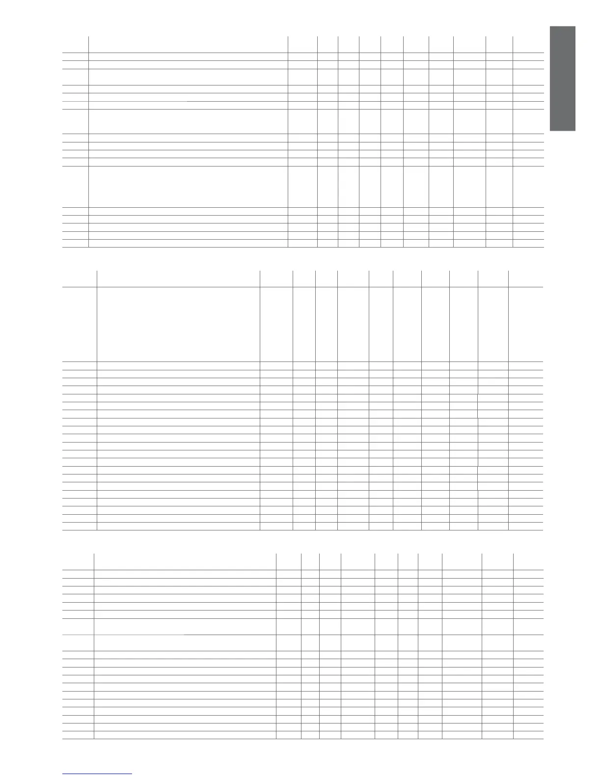
4.3.3 Antifreeze/support heater setting parameters (A*)
display
indicat.
parameter and description default
level
min. max. UOM variat. default visibility supervis.
variable
Modbus variable
type
A01 Alarm set point antifreeze/low ambient temperature (air/air) U A07 A04 °C/°F 0.1 30 - 11 (R/W) 11 Analog
A02 Differential for antifreeze/low ambient temperature alarm (air/air) U 3 1220 °C °F 0.1 50 - 12 (R/W) 12 Analog
A03 Bypass time for antifreeze alarm/low ambient temp. when turning on the unit
in heating mode
U 0 150 s 1 0 - 22 (R/W) 229 Integer
A04 Set point for the activation of antifreeze heater/auxiliary heater U A01 r16 °C/°F 0.1 50 AA 13 (R/W) 13 Analog
A04 Antifreeze/support heater set point differential U 0 200 °C/°F 0.1 70 AR 77 (R/W) 77 Analog
A05 Diff. for antifreeze heater/auxiliary heater U 3 500 °C/°F 0.1 10 - 14 (R/W) 14 Analog
A06 Auxiliary heater probe
0= Control probe see (see Table 5.a)
1= Antifreeze probe see (see Table 5.a)
F 0 1 Flag 1 0 - 6 (R/W) 6 Digital
A07 Antifreeze alarm set point limit F -400 1760 °C °F 0.1 -400 - 15 (R/W) 15 Analog
A08 Auxiliary heater set point in heating mode U A01 r16 °C °F 0.1 250 AA 16 (R/W) 16 Analog
A08 Antifreeze/support heater set point differential U 0 200 °C °F 0.1 70 AR 78 (R/W) 78 Analog
A09 Auxiliary heater differential in heating mode U 3 500 °C/°F 0.1 30 - 17 (R/W) 17 Analog
A10 Antifreeze automatic start up
0= disabled function
1= Heaters and pump on at the same time on A4/A8
2= Heaters and pump on indipendently on A4/A8
3= Heaters ON on A4/A8
U 0 3 1 0 - 23 (R/W) 230 Integer
A11 Auxiliary heater 2 set point in heating U A01 r16 °C/°F 0.1 250 AA 67 (R/W) 67 Analog
A11 Support heater 2 differential in heating U 0 200 °C/°F 0.1 70 AR 79 (R/W) 79 Analog
A12 T diff. set point for dirty fi lters (air/air) U 0 1760 °C/°F 0.1 150 - 57 (R/W) 57 Analog
A13 Outlet limit set point in freecooling conditions U A07 r16 °C/°F 0.1 30 - 80 (R/W) 80 Analog
A14 Antifreeze alarm set point from EVD U A07 A04 °C/°F 0.1 30 - 82 (R/W) 82 Analog
Table 4.c
4.3.4 Probe reading parameters (b*)
display
indicat.
parameter and description default
level
min. max. U.O.M. variat. default visibility supervis.
variable
Modbus variable
type
b00 Confi g. of probe to be shown on the display
0= probe B1 1= probe B2
2= probe B3 3= probe B4
4= probe B5 5= probe B6
6= probe B7 7= probe B8
8= set point without compensation
9= dynamic set point with possible compensation
10= remote ON/OFF digital input status
11= µAD probe
U 0 11 N 1 0 - 24 (R/W) 231 integer
b01 Value read by probe B1 D 0 0 °C /°F - 0 - 102 (R) 102 Analog
b02 Value read by probe B2 D 0 0 °C /°F - 0 - 103 (R) 103 Analog
b03 Value read by probe B3 D 0 0 °C /°F - 0 - 104 (R) 104 Analog
b04 Value read by probe B4 D 0 0 °C /°F/Dbar - 0 - 105 (R) 105 Analog
b05 Value read by probe B5 D 0 0 °C /°F - 0 X 106 (R) 106 Analog
b06 Value read by probe B6 D 0 0 °C /°F - 0 X 107 (R) 107 Analog
b07 Value read by probe B7 D 0 0 °C /°F - 0 X 108 (R) 108 Analog
b08 Value read by probe B8 D 0 0 °C /°F/Dbar - 0 X 109 (R) 109 Analog
b09 Driver 1 evaporator temperature D 0 0 °C /°F - 0 V 110 (R) 110 Analog
b10 Driver 1 evaporator pressure D 0 0 Dbar - 0 V 111 (R) 111 Analog
b11 Driver 1 superheating D 0 0 °C /°F - 0 V 112 (R) 112 Analog
b12 Driver 1 saturation temperature D 0 0 °C /°F - 0 V 113 (R) 113 Analog
b13 Driver 1 valve position D 0 1000 % - 0 V 114 (R) 114 Analog
b14 Driver 2 evaporator temperature D 0 0 °C /°F - 0 XV 115 (R) 115 Analog
b15 Driver 2 evaporator pressure D 0 0 Dbar - 0 XV 116 (R) 116 Analog
b16 Driver 2 superheating D 0 0 °C /°F - 0 XV 117 (R) 117 Analog
b17 Driver 2 saturation temperature D 0 0 °C /°F - 0 XV 118 (R) 118 Analog
b18 Driver 2 valve position D 0 1000 % - 0 XV 119 (R) 119 Analog
b19 Temp. probe at the outlet of the external coil c1 D 0 0 °C /°F - 0 V 120 (R) 120 Analog
b20 Temp. probe at the outlet of the external coil c12 D 0 0 °C /°F - 0 XV 121 (R) 121 Analog
b21 Terminal probe (for µAD terminal) D -400 800 °C /°F 0.1 0 - 128 (R) 128 Analog
Table 4.d
4.3.5 Compressor setting parameters (c*)
display
indicat.
parameter and description default
level
min. max. U.O.M. variat. def. visib. supervis.
variable
Modbus variabile
type
c01 Minimum on time U 0 999 s 1 60 - 25 (R/W) 232 Integer
c02 Minimum off time U 0 999 s 1 60 - 26 (R/W) 233 Integer
c03 Delay between 2 starts of the same compressor U 0 999 s 1 360 - 27 (R/W) 234 Integer
c04 Delay between starts of the 2 compressors U 0 999 s 1 10 - 28 (R/W) 235 Integer
c05 Delay between 2 shut-downs of the 2 compressors U 0 999 s 1 0 - 29 (R/W) 236 Integer
c06 Delay at start-up U 0 999 s 1 0 - 30 (R/W) 237 Integer
c07 Delay in switching on the compressor after switching on the pump/inlet
fan (air/air)
U 0 999 s 1 20 - 31 (R/W) 238 Integer
c08 Delay in switching OFF the compressor after switching OFF the pump/
inlet fan (air/air)
U 0 150 min 1 1 - 32 (R/W) 239 Integer
c09 Maximum compressor operating time in tandem U 0 60 min 1 0 - 33 (R/W) 240 Integer
c10 Compressor 1 timer D 0 8000 100 hours - 0 - 122 (R) 122 Analog
c11 Compressor 2 timer D 0 8000 100 hours - 0 - 123 (R) 123 Analog
c12 Compressor 3 timer D 0 8000 100 hours - 0 - 124 (R) 124 Analog
c13 Compressor 4 timer D 0 8000 100 hours - 0 - 125 (R) 125 Analog
c14 Operation timer threshold U 0 100 100 hours 1 0 - 34 (R/W) 241 Integer
c15 Hour counter evaporator pump/fan 1 D 0 8000 100 hours - 0 - 126 (R) 126 Analog
c16 Hour counter condenser backup pump/fan 2 D 0 8000 100 hours - 0 - 127 (R) 127 Analog
c17 Minimum time between 2 pump starts U 0 150 min 1 30 - 35 (R/W) 242 Integer
c18 Minimum pump ON time U 0 15 min 1 3 - 36 (R/W) 243 Integer
c19 Delay between valve and compressor U 0 100 s 1 3 - 125(R/W) 332 Integer
Table 4.e
 Loading...


