28
ENGLISH
µC
2
SE - +030220426 - rel. 2.0 - 03.08.2009
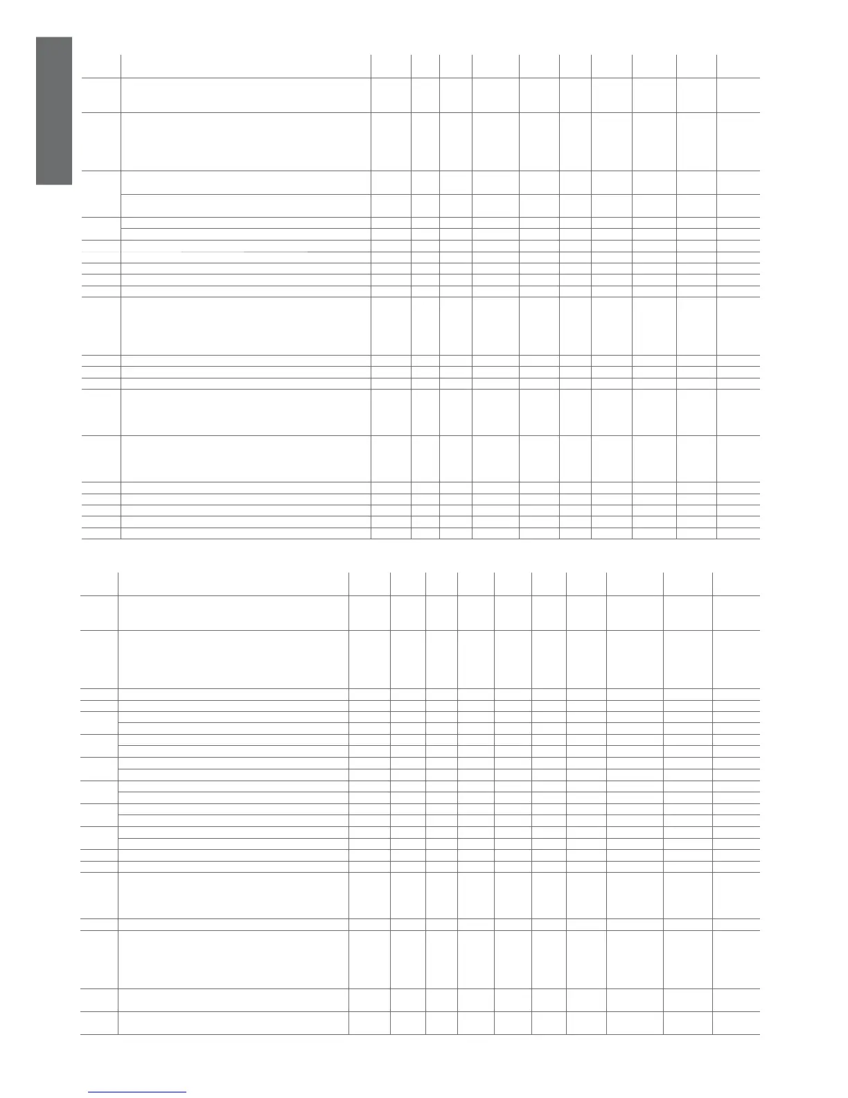
4.3.6 Defrost setting parameters (d*)
display
indicat.
parameter and description default
level
min. max. U.O.M. variat. default visibility supervis.
variable
Modbus variable
type
d01 Defrosting cycle/Condenser antifreeze
0= no;
1= sì, con sbrinamento unifi cato yes, with shared defrosting
U 0 1 Flag 1 0 - 7 (R/W) 7 Digital
d02 Time-or temperature-based defrosting
0= time
1= temp. - press
2= pressure start, temperature end
3= activate sliding defrost
U 0 3 Flag 1 0 D 90 (R/W) 297 Integer
d03
Start defrosting temperature
Condenser antifreeze alarm set point
U -400 d04 °C/°F 0.1 -50 DN 19 (R/W) 19 Analog
Start defrosting pressure
Condenser antifreeze alarm set point
U /11 d04 Dbar 0.1 35 DP 18 (R/W) 18 Analog
d04
End defrost temperature U d03 /12 Dbar 0.1 140 DP 20 (R/W) 20 Analog
End defrost pressure d03 1760 °C/°F 0.1 200 DN 21 (R/W) 21 Analog
d05 Min. time to start a defrosting cycle U 10 150 s 1 10 D 37 (R/W) 244 Integer
d06 Min. duration of a defrosting cycle U 0 150 s 1 0 D 38 (R/W) 245 Integer
d07 Max. duration of a defrosting cycle U 1 150 min 1 5 D 39 (R/W) 246 Integer
d08 Delay between 2 defrosting cycle requests within the same circuit U 10 150 min 1 30 D 40 (R/W) 247 Integer
d09 Defrosting delay between the 2 circuits U 0 150 min 1 10 D 41 (R/W) 248 Integer
d10 Defrost by external contact
0= disables function
1= external contact start
2= external contact end
3= external contact start and end
F 0 3 Flag 1 0 D 42 (R/W) 249 Integer
d11 Antifreeze heater in defrost U 0 1 Flag 1 0 D 9 (R/W) 9 Digital
d12 Waiting time before defrosting F 0 3 min 1 0 D 43 (R/W) 250 Integer
d13 Waiting time after defrosting F 0 3 min 1 0 D 44 (R/W) 251 Integer
d14 End defrosting with 2 refrigerating circuits
0= Indipendent
1= If both at end defrost
2= If at least one at end defrost
F 0 2 Flag 1 0 D 45 (R/W) 252 Integer
d15 Start defrost with 2 circuits
0= Indipendent
1= If both at start defrost
2= If at least one at start defrost
F 0 2 Int 1 0 D 46 (R/W) 253 Integer
d16 Forced ventilation time at the end of the defrosting F 0 360 s 1 0 D 47 (R/W) 254 Integer
d17 Set/enable light defrost F 0 800 °C/°F 0.1 0 D 22 (R/W) 22 Analog
d18 Max. outside temperature (sliding defrost) F -400 800 °C/°F 0.1 -100 D 62 (R/W) 62 Analog
d19 Start defrost differential (sliding defrost) F -400 800 °C/°F/bar 0.1 30 D 63 (R/W) 63 Analog
d20 Outside temperature differential (sliding defrost) F 10.0 800 °C/°F 0.1 100 D 64 (R/W) 64 Analog
Table 4.f
4.3.7 Fan setting parameters (F*)
display
indicat.
parameter and description default
level
min. max. U.O.M. variat. def. visibility supervis.
variable
Modbus variable
type
F01 Enable Fan output
0=not present
1=present
F 0 1 Flag 1 0 - 10 (R/W) 10 Digital
F02 Fan operating mode
0= always ON
1= depending ON the compressor (in parallel operation mode)
2= depending ON the compressors in ON/OFF control
3= depending ON the compressors in speed control mode
U 0 3 Int 1 0 F 48 (R/W) 255 Integer
F03 Min. voltage threshold for Triac F 0 F04 step 1 35 F 49 (R/W) 256 Integer
F04 Max. voltage threshold for Triac F F03 100 step 1 75 F 50 (R/W) 257 Integer
F05
Speed temp. set point in Cooling mode U -400 1760 °C/°F 0.1 350 FN 24 (R/W) 24 Analog
Pressure value for min. speed Cooling U /11 /12 Dbar 0.1 130 FP 23 (R/W) 23 Analog
F06
Differential value for max. speed Cooling U 0 500 °C/°F 0.1 100 FN 26 (R/W) 26 Analog
Pressure value for max. speed Cooling U 0 300 Dbar 0.1 30 FP 25 (R/W) 25 Analog
F07
Fan shut-down differential in Cooling mode U 0 500 °C/°F 0.1 150 FN 28 (R/W) 28 Analog
Fan shut-down pressure in Cooling mode U 0 F05 Dbar 0.1 50 FP 27 (R/W) 27 Analog
F08
Speed temp. set point in Heating mode U -400 1760 °C/°F 0.1 350 FN 30 (R/W) 30 Analog
Pressure value for max speed in Heating U /11 /12 Dbar 0.1 130 FP 29 (R/W) 29 Analog
F09
Max. speed diff. in Heating mode U 0 500 °C/°F 0.1 50 FN 32 (R/W) 32 Analog
Pressure value for max speed in Heating U 0 F08 Dbar 0.1 40 FP 31 (R/W) 31 Analog
F10
Fan shutdown diff. in Heating mode U 0 F08 °C/°F 0.1 50 FN 34 (R/W) 34 Analog
Pressure to turn OFF the fan in Heating U 0 300 Dbar 0.1 30 FP 33 (R/W) 33 Analog
F11 Fan starting time U 0 120 s 1 0 F 51 (R/W) 258 Integer
F12 Triac impulse duration (fan start) F 0 10 s 1 2 F 52 (R/W) 259 Integer
F13 Fan management in defrost mode
0= Fans deactivated
1= Fans in chiller mode
2= Maximum speed after defrost
F 0 2 Int 1 0 F 53 (R/W) 260 Integer
F14 Fan with high condensing temperature when starting U 0 999 - 1 0 FN 91 (R/W) 298 Integer
F15 Low noise activation
0= deactivated
1= activated in cooling
2= activated in heating
3= activated in cooling and heating
U 0 3 - 1 0 F 85 (R/W) 292 Integer
F16 Low noise diff. in cooling F 0 500 °C/°F/
bar
0.1 0 L 35 (R/W) 35 Analog
F17 Low noise diff. in heating F 0 500 °C/°F/
bar
0.1 0 L 36 (R/W) 36 Analog
Table 4.g
 Loading...


