V Driver
EV Driver
Expansion
board
EV driver
ENGLISH
µC
2
SE - +030220426 - rel. 2.0 - 03.08.2009
7. CONNECTIONS, ACCESSORIES AND OPTIONS
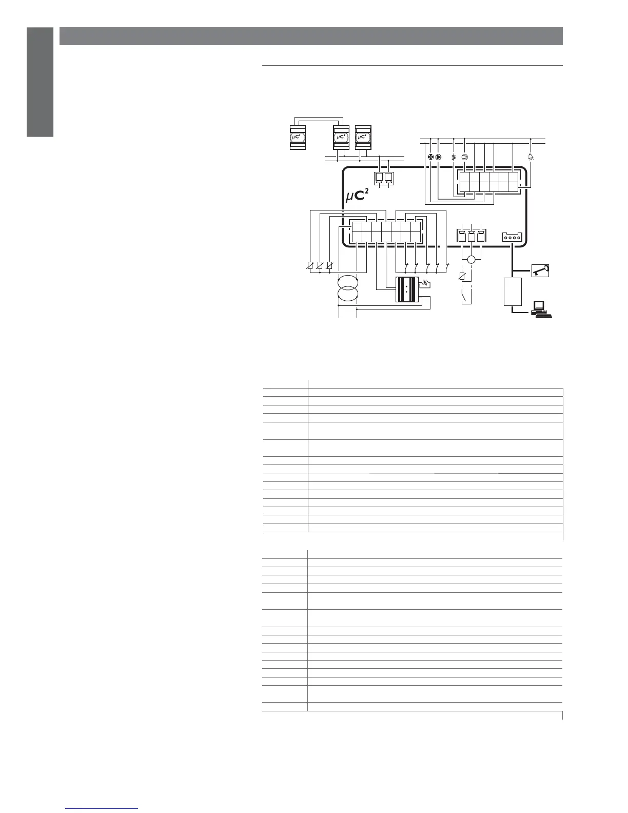
7.1 Connection diagram
Below is the connection diagram for the µC
2
SE.
Panel version
I/O layout
µC
2
SE Description
B1 Control probe (Evaporator inlet/ambient)
B2 Protection probe (evaporator outlet/outlet)
B3 Condenser/outside temperature probe
B4 ( universal) Condenser pressure probe
ID1* Flow switch – thermal overload circuit 1 – cooling/heating – end defrost circuit 1 – step 1
condensing unit – second set point
ID2* Flow switch – thermal overload 1 circuit – cooling/heating – end defrost circuit 1 – step 2
condensing unit – second set point
ID3 High pressure circuit 1
ID4 Low pressure circuit 1
ID5 Remote ON/OFF – reverse cycle condensing unit if reversible
Y1 Ramp circuit 1 (condenser)
C1/2-NO1 Compressor 1
C1/2-NO2 Heater or reversing valve in 1st circuit
C3/4-NO3 Fan 1/evaporator pump
C3/4-NO4 Compressor 2 (capacity-control compressor 1)
C5-NO5 Alarm or reversing valve
Table 7.a
Expansion Description
B5 Output probe in common with 2 evaporators (only with 2 circuits)
B6 Circuit 2 protection probe (2
nd
evaporator output)
B7 2
nd
condenser temperature probe
B8 ( universal) 2
nd
condenser pressure probe
ID6** Flow switch – thermal overload circuit 2 – end defrost circuit 2 – step 4 condensing unit –
second set point
ID7** Flow switch – thermal overload circuit 2 – end defrost circuit 2 – step 4 condensing unit– second
set point
ID8 High pressure circuit 2
ID9 Low pressure circuit 2
ID10
Y2 Ramp circuit 2 (condenser)
C6/7-NO6 Compressor 3 (1 in 2nd circuit)
C6/7-NO7 Heater or reversing valve in 2nd circuit
C8/9-NO8 Fan 2/condenser pump/backup
C8/9-NO9 Compressor 4 (capacity-control compressor 2) or reversing valve circuit 1 or reversing valve
circuit 2
C10-NO10 Warning or reversing valve circuit 2
Table 7.b
*= Any of the options for P08 can be selected (see Table 5.11)
**= Any of the options for P08 can be selected, except for E/I and E/I delay.
Fig. 7.a
 Loading...


