33
ENGLISH
µC
2
SE - +030220426 - rel. 2.0 - 03.08.2009
-
-
-
-
-
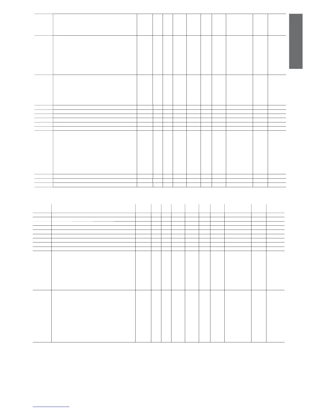
Defrost status
bit 0= Defrost circuit 1
bit 1= Defrost circuit 2
bit 2= Fan Defrost circuit 1
bit 3= Fan Defrost circuit 2
D 0 255 - 0 134 (R) 341 Integer
- Controls from the UAD:
bit0= terminal status (0= not connected; 1= available)
bit2; bit1= mode set from µAD (00= AUTO; 01= cooling; 10=
heating)
bit3= enable dehumidifi cation
bit4= enable humidifi cation
bit5= terminal probe alarm
bit6= activate boiler output
bit7= 0= process mode active; 1= process mode disabled
D 0 1023 1 0 135 (R/W) 342 Integer
- Signals to the µAD
bit0= cool/heat request from uAD in progress
bit1= cool/heat request accepted from µAD (1= cooling; 0=
heating)
bit2= start fans
bit3= alarm active on µCH
bit4= RTC available on µCH2 SE
D 0 255 - 0 136 (R) 343 Integer
- DTE value saved in EEPROM D 0 0 - 0 98 (R) 98 Analog
- Internal set point compensated in the event of autotuning D 0 0 - 0 97 (R) 97 Analog
- Ambient set point (from µAD) D -400 1760 0,1 0 95 (R/W) 95 Analog
- Set point variation from µAM (µedronic) D -100 100 0,1 0 96 (R/W) 96 Analog
- Differential for the ambient set point D -100 100 0,1 0 94 (R/W) 94 Analog
- Controls by the µAD from save D 0 32767 1 0 - 137 (R/W) 344 Integer
- “Active alarm signal:
bit0= probe alarm (E1,E2,E,E4,E5,E6,E7,E8)
bit1= high pressure alarm (HP1, HP2)
bit2= low pressure alarm (LP1, LP2)
bit3= fl ow switch alarm (FL)
bit4= expansion communication alarm (ESP)
bit5= EE2PROM alarm (EPB)
bit6= antifreeze alarm (A1, A2)
bit7= thermal overload alarm (TP, TP1, TP2)
bit8= hour counter alarm (H1, H2, H, H4)”
D 0 32767 1 0 - 128 (R/W) 335 Integer
- Terminal humidity probe (per terminal µAD) D 0 1000 % 0,1 0 129 (R/W) 129 Analog
- Reset alarms D 0 1 1 0 78 (R/W) 78 Digital
- Digital input B D 0 1 - 0 79 (R) 79 Digital
Table 4.m
4.3.13 Supervisor-only variables
display
indicat.
parameter and description default
level
min. max. U.O.M. variat. def. visibility supervis.
variable
Modbus variable
type
- Indicates the unit parameter (Carel SV communication) F 0 250 - 108 (R) 207 Integer
- Gain constant for pressure probe calibration F 0 16000 - 1000 (R) 207 Integer
- Offset constant for pressure probe calibration F -8000 8000 - 0 (R) 207 Integer
- Compressor 1 operating hours D 0 8000 - 0 (R) 207 Integer
- Compressor 2 operating hours D 0 8000 - 0 (R) 207 Integer
- Compressor 3 operating hours D 0 8000 - 0 (R) 207 Integer
- Compressor 4 operating hours D 0 8000 - 0 (R) 207 Integer
- Compressor pump operating hours D 0 8000 - 0 (R) 207 Integer
- Evaporator pump operating hours D 0 8000 - 0 (R) 207 Integer
- Alarms/warnings for EVD1:
bit0= low superheat alarm
bit1= EEPROM alarm
bit2= probe alarm
bit3= MOP warning
bit4= LOP warning
bit5= high suction temperature warning
bit6= valve open after power failure alarm
bit7= fl at battery alarm
D 0 0 - 0 (R) 207 Integer
- Controls/status indicators for EVD1:
bit0; bit1= comp. load step (0= 0%; 1= 50%; 2= 100%)
bit2= standby circuit 2 (0= ON; 1= standby)
bit3= chiller/pump circuit 2 (0= chiller; 1= pump)
bit4= defrost circuit 2 (0= no defrost; 1= defrost)
bit5= forced valve closing (for pump down)
bit6= enable smart defrost
bit7= enable low noise
bit8= type of condenser probe (0= temp/1= press)
bit9= condenser temp/press probe available
bit10= restart unit after valve open alarm (set in reset_alarms)
bit11= enable control for driver 2
D 0 0 - 0 (R) 207 Integer
 Loading...


