32
ENGLISH
µC
2
SE - +030220426 - rel. 2.0 - 03.08.2009
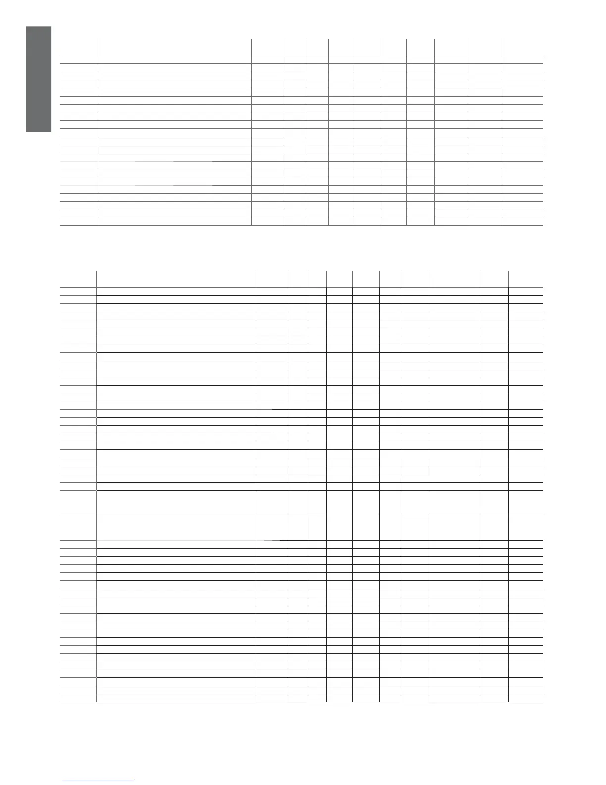
4.3.12 Timer setting parameters (t*)
display
indicat.
parameter and description default
level
min. max. U.M. variat. def. visibility supervis.
variable
Modbus variabile type
t01 RTC hours U 0 23 h 1 0 W 129(R/W) 336 Integer
t02 RTC minutes U 0 59 min 1 0 W 130 (R/W) 337 Integer
t03 RTC day U 1 31 g 1 1 W 131 (R/W) 338 Integer
t04 RTC month U 1 12 mesi 1 1 W 132 (R/W) 339 Integer
t05 RTC year U 0 99 anni 1 6 W 133 (R/W) 340 Integer
t06 Start hours for 2nd set point in cooling U 0 23 h 1 0 W 92 (R/W) 299 Integer
t07 Start minutes for 2nd set point in cooling U 0 59 min 1 0 W 93 (R/W) 300 Integer
t08 End hours for 2nd set point in cooling U 0 23 h 1 0 W 94 (R/W) 301 Integer
t09 End minutes for 2nd set point in cooling U 0 59 min 1 0 W 95 (R/W) 302 Integer
t10 Start hours for 2nd set point in heating U 0 23 h 1 0 W 9 (R/W) 303 Integer
t11 Start minutes for 2nd set point in heating U 0 59 min 1 0 W 97 (R/W) 304 Integer
t12 End hours for 2nd set point in heating U 0 23 h 1 0 W 98 (R/W) 305 Integer
t13 End minutes for 2nd set point in heating U 0 59 min 1 0 W 99 (R/W) 306 Integer
t14 Start hours for 2nd low-noise in cooling U 0 23 h 1 23 W 100 (R/W) 307 Integer
t15 Start minutes for 2nd low-noise in cooling U 0 59 min 1 0 W 101 (R/W) 308 Integer
t16 End hours for 2nd low-noise in cooling U 0 23 h 1 7 W 102 (R/W) 309 Integer
t17 End minutes for 2nd low-noise in cooling U 0 59 min 1 0 W 103 (R/W) 310 Integer
t18 Start hours for 2nd low-noise in heating U 0 23 h 1 23 W 104 (R/W) 311 Integer
t19 Start minutes for 2nd low-noise in heating U 0 59 min 1 0 W 105 (R/W) 312 Integer
t20 End hours for 2nd low-noise in heating U 0 23 h 1 7 W 106 (R/W) 313 Integer
t21 End minutes for 2nd low-noise in heating U 0 59 min 1 0 W 107 (R/W) 314 Integer
Table 4.l
4.3.13 Supervisor-only variables
display
indicat.
parameter and description default
level
min. max. U.O.M variat. def. visibility supervis.
variable
Modbus variable
type
- Circuit 1 alarm D 0 1 - 0 41 (R) 41 Digital
- Circuit 2 alarm D 0 1 - 0 42 (R) 42 Digital
- EVD valve 1 alarm D 0 1 - 0 43 (R) 43 Digital
- EVD valve 2 alarm D 0 1 - 0 44 (R) 44 Digital
- General alarm D 0 1 - 0 45 (R) 45 Digital
- Probe alarm D 0 1 - 0 46 (R) 46 Digital
- Compressor warning D 0 1 - 0 47 (R) 47 Digital
-
Compressor error alarm D 0 1 - 0 25 (R) 25 Digital
- EVD 1 warning D 0 1 - 0 48 (R) 48 Digital
- EVD 2 warning D 0 1 - 0 49 (R) 49 Digital
- General warning D 0 1 - 0 50 (R) 50 Digital
- Temperature warning D 0 1 - 0 51 (R) 51 Digital
- Fan warning D 0 1 - 0 52 (R) 52 Digital
- DTE/DTC alarm D 0 1 - 0 77 (R) 77 Digital
- Digital input 1 D 0 1 - 0 53 (R) 53 Digital
- Digital input 2 D 0 1 - 0 54 (R) 54 Digital
- Digital input 3 D 0 1 - 0 55 (R) 55 Digital
- Digital input 4 D 0 1 - 0 56 (R) 56 Digital
- Digital input 5 D 0 1 - 0 57 (R) 57 Digital
- Digital input B4 D 0 1 - 0 58 (R) 58 Digital
- Digital input 1 D 0 1 1 0 59 (R/W) 59 Digital
- Digital input 2 D 0 1 1 0 60 (R/W) 60 Digital
- Digital input 3 D 0 1 1 0 61 (R/W) 61 Digital
- Digital input 4 D 0 1 1 0 62 (R/W) 62 Digital
- Digital input 5 D 0 1 1 0 63 (R/W) 63 Digital
- Standby/On status
0= Standby
1= On
D 0 1 1 0 64 (R/W) 64 Digital
- Heating/Cooling status:
0= Heating
1= Cooling
D 0 1 1 1 65 (R/W) 65 Digital
- Gain constant for probe 1 calibration F 0 8000 - 1000 5 (R) 212 Integer
- Gain constant for probe 2 calibration F 0 8000 - 1000 6 (R) 213 Integer
- Gain constant for probe 3 calibration F 0 8000 - 1000 7 (R) 214 Integer
- Gain constant for probe 4 calibration F 0 8000 - 1000 8 (R) 215 Integer
- Offset constant for probe 1 calibration F -8000 8000 - 0 9 (R) 216 Integer
- Offset constant for probe 2 calibration F -8000 8000 - 0 10 (R) 217 Integer
- Offset constant for probe 3 calibration F -8000 8000 - 0 11 (R) 218 Integer
- Offset constant for probe 4 calibration F -8000 8000 - 0 12 (R) 219 Integer
Digital input 6 D 0 1 - 0 66 (R) 66 Digital
- Digital input 7 D 0 1 - 0 67 (R) 67 Digital
- Digital input 8 D 0 1 - 0 68 (R) 68 Digital
- Digital input 9 D 0 1 - 0 69 (R) 69 Digital
- Digital input 10 D 0 1 - 0 70 (R) 70 Digital
- Digital input B8 D 0 1 - 0 71 (R) 71 Digital
- Digital output 6 D 0 1 1 0 72 (R/W) 72 Digital
- Digital output 7 D 0 1 1 0 73 (R/W) 73 Digital
- Digital output 8 D 0 1 1 0 74 (R/W) 74 Digital
- Digital output 9 D 0 1 1 0 75 (R/W) 75 Digital
- Digital output 10 D 0 1 1 0 76 (R/W) 76 Digital
- Password to control outputs from the supervisor D 0 8000 1 0 13 (R/W) 220 Integer
 Loading...


