51
ON
OFF r01 r01+r07+r02/4
r01+r07+r02*3/4
r01+r07 r01+r07+r02/2r01+r07+r02/2 r01+r07+r02r01+r07+r02
ON
OFF
r03-r07-r02/4r03-r07-r04
r03-r07+r04/4
r03
r03-r07
r03-r07+r04*3/4r03-r07+r04*3/4
r03 r03+r12
r10
r11
ENGLISH
µC
2
SE - +030220426 - rel. 2.0 - 03.08.2009
When stopping, the valve is managed fi rst and then the actual compressor as a whole. Both FIFO logic
and timed operation will involve either one circuit or the other. The activation and deactivation of the valves
are not subject to timers, but rather only a hysteresis that is equal to the set point and the differential of
the step (in fact the valve performs the same function as a hermetic compressor).
r05=3: direct correspondence between the digital inputs and the compressor relays (condensing units
only).
- Type of compressor control
r06: This parameter is used to set the logic for maintaining the set point:
r06= 0: proportional on inlet
r06= 1: proportional on inlet + dead zone (see Dead zone, below)
r06= 2: proportional on outlet
r06= 3: proportional on outlet with dead zone
r06= 4: on outlet by time with dead zone (see timed outlet temperature control)
DEAD ZONE
The dead zone essentially shifts the proportional band from the set
point by the value set for the parameter r07.This parameter is valid in
all confi gurations if enabled (for r07≠0: dead zone set and enabled).
Key Figure 5.b.c:
r06: enable the dead zone (enabled if r06=1 or 3)
r07: dead zone
r01: cooling set point
r02: cooling differential
In chiller (cooling) mode, the dead zone moves the cooling proportional band above the set point by the
value r07.
Key Figure 5.b.d:
r06: enable the dead zone (enabled if r06=1 or 3)
r07: dead zone
r03: heating set point
r04: heating differential
In heat pump (heating) mode, the dead zone moves the heating proportional band below the set point
by the value r07.
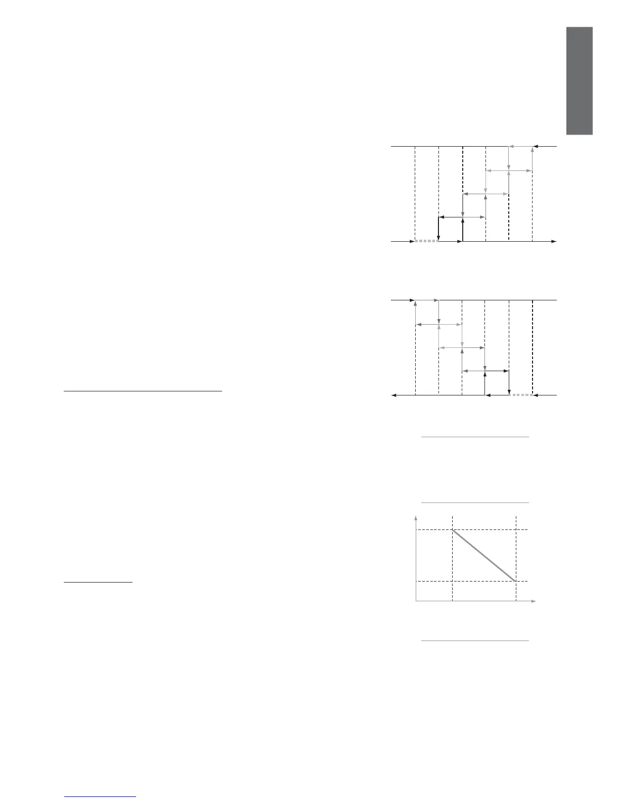
Outlet temperature control by time r06 = 4 (only chiller)
This type of control is based on the need to maintain the outlet temperature as constant as possible,
despite the load being variable or the reduced inertia of the system.
The logic has the aim of keeping the temperature inside the dead zone.
If outside the zone, the compressors will be activated with the logic described below, so as to return
inside the dead zone, neither too quickly (using an integral or derivative), nor too slowly, with fi xed time
logic. There are two logical times involved: the activation time and deactivation time.
- Dead zone differential
r07: ( see dead zone)
- Activation delay at lower limit of r07 (if r06 = 4)
r08: The value set is used in the control algorithm (see timed outlet temperature control) as the
maximum time (at the start of the differential) for the activation of the compressors.
- Activation delay at upper limit of r07 (if r06 = 4)
r09: The value set is used in the control algorithm (see timed outlet temperature control) as the
minimum time (at the end of the differential) for the activation of the compressors.
Activation time (cooling)
The activation time is not a set parameter, but rather the combination of two set parameters, that is, r08
and r09. When the temperature leaves the dead zone, the activation time is equal to r08, while at the end
of the differential r02 the activation time is equal to r09.
Inside the differential r02, the activation time varies linearly between r08 and r09.
This means that as the temperature moves away from the set point, the times are reduced and the
esponse of the process becomes more dynamic.
- Deactivation delay at upper limit of r12 (if r06 = 4)
r10: The value set is used in the control algorithm (see timed outlet temperature control) as the
maximum time (at the set point) for the deactivation of the compressors.
- Deactivation delay at lower limit of r12 (if r06 = 4)
r11: The value set for this parameter is used in the control algorithm (see timed outlet temperature
control) as the minimum time (at the end of the deactivation differential) for the deactivation of the
compressors.
Fig. 5.b.c
Fig. 5.b.d
Fig. 5.b.e
activation time
temperature
time
dead zone comp. act. differential
 Loading...


