ENGLISH
µC
2
SE - +030220426 - rel. 2.0 - 03.08.2009
In this case, the display will be as follows:
operating mode LED OFF;•
cooling heating fl ag not switched (not detected by the supervisor);•
antifreeze alarm A01 (remains active even at the end of the special operation if the unit was previously •
ON, deactivated by manual reset or in standby).
A10=3: heaters ON based on the respective set point A04 and A08.
Do not use with H1= 6
- Antifreeze heater 2 set point in defrost/auxiliary in heating
A11: Heater 2 set point in heating, the control of the auxiliary heaters has been separated, each having its
own activation set point (see A08).
- Dirty fi lter signal set point (air/air units only)
A12: Set point for the dirty fi lter signal based on B1-B2, the deactivation differential is A05
Valid in the following conditions:•
air-air units;•
B1 is confi gured;•
outlet limit active;•
freecooling not active;•
at least 1 compressor ON.•
The warning is reset automatically in the following conditions:
air-air units;•
B1 is confi gured;•
outlet limit active;•
freecooling not active.•
- Outlet limit set point in freecooling conditions
A13: With freecooling active, and only when the compressors are off, this represents the outlet limit.
When the compressors are on, even if freecooling is active, the outlet limit alarm is bypassed and the
antifreeze alarm is used.
- Antifreeze alarm set point from EVD
A14: With the EVD connected in the tLAN, A14 represents the evaporation temperature (sent by the EVD)
below which the antifreeze alarm is activated; when the alarm is active, the compressors in the circuit
affected are switched off, while the pump remains on to reduce the possibility of freezing. Manual reset
(or automatic, depending on parameter P05), only occurs when the water temperature returns within the
operating limits (that it, exceeds A14+A02
• Probe readings: parameters (B*)
- Select probe to be shown on display.
b00: Sets the probe reading to be displayed.
0= probe B1
1= probe B2
2= probe B3
3= probe B4
4= probe B5
5= probe B6
6= probe B7
7= probe B8
8= set point without compensation
9= dynamic set point with possible compensation
10= remote ON/OFF digital input status
For the list of parameter-probe associations see Table 4.d
Note: probes that are not present cannot be selected.
• Compressor settings: parameters (c*)
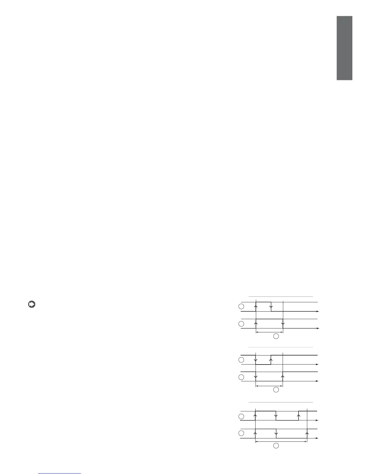
- Minimum ON time
c01: This establishes the time that the compressor must remain ON for when started, even if the stop
signal is sent.
Key:
signal;1.
compressor;2.
min. ON time-interval.3.
- Minimum OFF time
c02: This establishes the time that the compressor must remain OFF for when stopped, even if the start
signal is sent. The compressor LED fl ashes in this phase.
Key:
signal;1.
compressor;2.
min. OFF time-interval.3.
- Delay between 2 starts of the compressor
c03: This sets the minimum time that must elapse between two successive starts of the same compressor
(determines the maximum number of starts per hour for the compressor). The compressor LED fl ashes in this
phase. If by mistake the user enters a value lower than the sum of C01 + C02, this parameter will be ignored and
only the times C01 and C02 will be considered.
Key:
signal;1.
compressor;2.
min. time-interval between two ON routins.3.
Fig. 5.a.c
Fig. 5.a.d
Fig. 5.a.e
 Loading...


