µRack
Cod. CAREL +03P220431 rel. 0.0 del 08/09/05 - preliminary version
14
5. Fan and inverter management
Inputs used:
• Discharge pressure probe
• Digital inputs for the fan safety devices
• Multifunction input for generic alarm (general discharge pressure switch)
Outputs used:
• Condenser fan outputs
• Condenser fan speed control (PWM output)
5.1. Fan management
The operation of the fans depends on the value read by the discharge pressure (or temperature) sensor.
One thermal overload is featured for each fan step. This has a settable immediate reset and will only be valid for the specific fan. In the default configuration,
“proportional band” control is set (parameter r21), and FIFO rotation (parameter r20).
5.1.1. Fan control
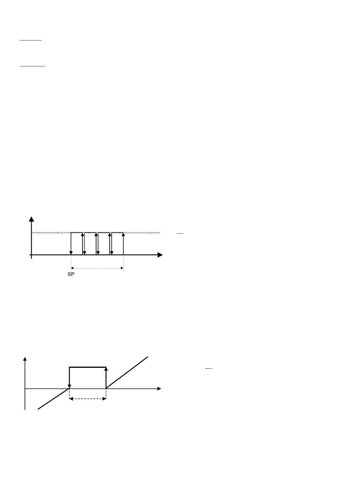
Proportional band
Proportional band control calculates, based on various parameters (SP, DF and the number of devices set) the points where the devices must switch on and off,
inside the differential band.
Figure 5.1 shows the activation points for a system with 4 steps.
Setting the parameters listed above, each individual step will have a differential as follows:
SP + 1 *DF/ (No. of steps) for the first;
SP + 2 *DF/ (No. of steps) for the second;
…
SP + DF for the last.
RP
DF
ON
OFF
Fig. 5.1
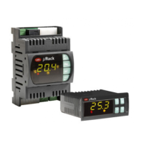
5.2. Dead band control
This type of control features the definition of a dead band to the side of the set point, within which no device is started or stopped.
The devices are activated when the measured value exceeds the limit to the right (measured value greater than SP + DZN, see Figure 5.2). The number of devices
to be activated varies according to the time elapsed outside of the dead band. The first device will start immediately, while the others will wait the set time
between starts.
Similarly, the devices are stopped when the measured value falls below the dead band (measured value less than the set point), and remains there for a period
equal to the time between device stop requests. In this case too, the first device stops immediately, while the others wait the delay time between stops.
The program will switch the devices on according to the start-up logic configured and the availability of the devices
5.2.1. 5.1.2 Fan rotation
The rotation of the fans, settable by parameter r20, is aimed at balancing the number of operating hours and starts of the different fans.
Rotation automatically excludes any fans with active alarms.
A fan with an active alarm is automatically stopped, and another will immediately be called, so as to satisfy the load.
Two different types of rotation can be set:
Key
:
SP Fan set point
DF Fan differential
RP Pressure read
Key
:
DOffZ Device deactivation zone
NZ Dead band
DOnZ Device activation zone
DZN Dead band differential
RP Discharge pressure read
SP Fan set point
DOffZ
DOnZ
Z
SP
DZN
RP
Fi
. 5.2