S&2ð
cod. Carel +030221826 rel. 2.0 dated 03/10/02
25
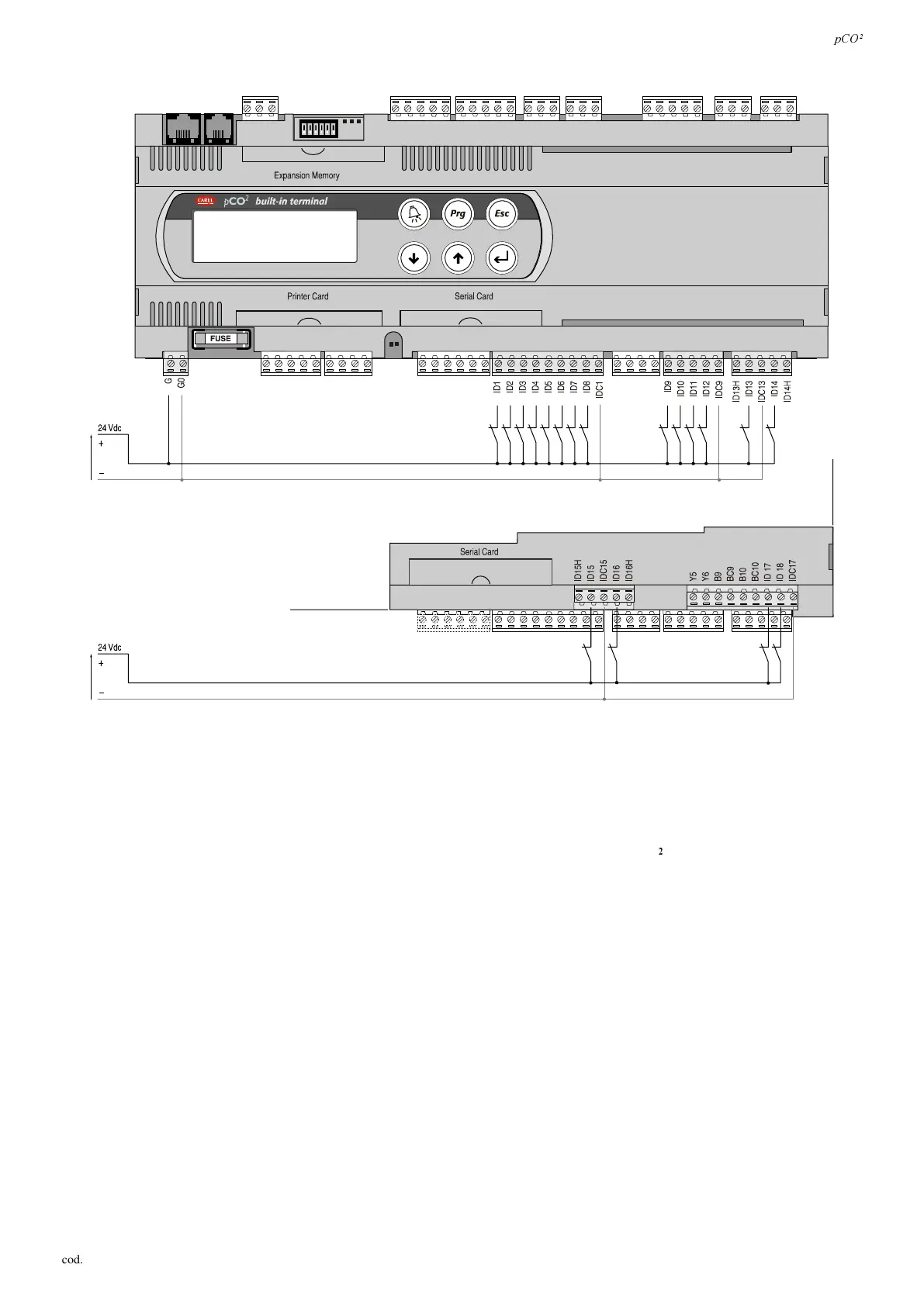
'LJLW D OLQSXW VSRZ HUHGDW9GF
)LJ
The following figure represents one of the more common connection diagrams for the 24Vdc digital inputs.
,03257$17:$51,1*6: to maintain the optical isolation of the digital inputs a separate power supply must be used just for
the digital inputs; Figs. 4.5.2.1 and .2 show the versions: MEDIUM (in full) and LARGE (limited to the terminals located more
internally, on the board).
The connection diagrams in Figs. 4.5.2.1 and .2, while being the more common and the more convenient, do not exclude the
possibility of powering the digital inputs LQGHSHQGHQWO\IURPWRWKHSRZHUVXSSO\WRWKHS&2
.
 Loading...


