S&2ð
cod. Carel +030221826 rel. 2.0 dated 03/10/02
26
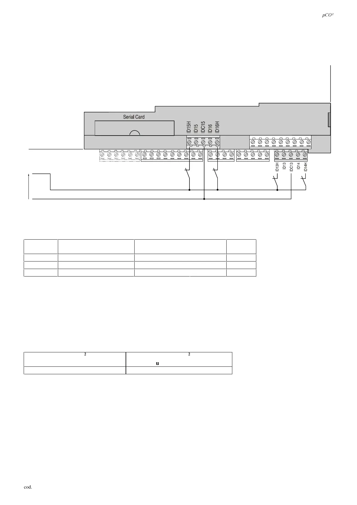
'LJLW D OLQSXW VSRZ HUHGDW9DF
The following figure represents one of the more common connection diagrams for the 230Vac digital inputs. Each group (see
0HDQLQJRI,2LQSXWV) can have different voltages. Within each the digital inputs are not independent, however: for example,
with reference to Fig. 4.5.3.1, the inputs ID15 and ID16, due to the common terminal, must be powered at the same voltage to
avoid dangerous short-circuits and/or the powering of lower-voltage circuits at 230Vac.
110÷230 Vac
L
N
)LJ
7DEOHVXPPDULVLQJ W KHGLJ LW DO LQSXWVDFFRUGLQJWRWKHDYDLODEOHYHUVLRQV
YHUVLRQ
QRRSWRLVRODWHGLQSXWV
DW9DF+]RU9GF
QRRSWRLVRODWHGLQSXWV
D9DFRU9DF+]
WRWDO
LQSXWV
60$//
8 0 8
0(',80
12 2 14
/$5*(
14 4 18
7DE
,03257$17:$51,1*6: do not connect other devices to the IDN inputs (for example, relay coils for sending signals to
other instruments). In the specific case of the inputs at 230Vac, a dedicated RC filter (typical characteristics: 100Ω, 0.5 µF,
630V) should be placed in parallel to the coil; Fig. 4.2.1.3 shows the part of the pCO
2
involving the terminals described. The
MEDIUM and LARGE models are very similar.
If safety devices (alarms) are connected to the digital inputs, SOHDVHNHHSWKHIROORZLQJLQPLQG: the presence of voltage at the
ends of the contact is a normal operating condition, while the absence of voltage is an alarm condition. In this way any
interruption (or disconnection) of the input can be signalled.
When remoting the analogue inputs, the cross section of the leads must be as reported in the following table (Tab. 4.5.4.2)
VL]HPP
IRUXSWRPORQJOHDGV
VL]HPP
IRUXSWRPORQJOHDGV
0,25 0,5
7DE
 Loading...


