S&2ð
cod. Carel +030221826 rel. 2.0 dated 03/10/02
32
S/$11(7:25.
As already mentioned, the pCO
2
controls can be connected to pLAN local network, allowing the communication of data and
information from one location (node) to another.
Each pCO
2
can be connected to a CAREL supervisory network, using the optional PCO2004850 cards.
The pCO
2
terminals can monitor the control variables (temperature, humidity, pressure, I/O, alarms) from one or more boards. If
one or more terminals are disconnected or malfunctioning, the control program continues to function correctly on each pCO
2
main board.
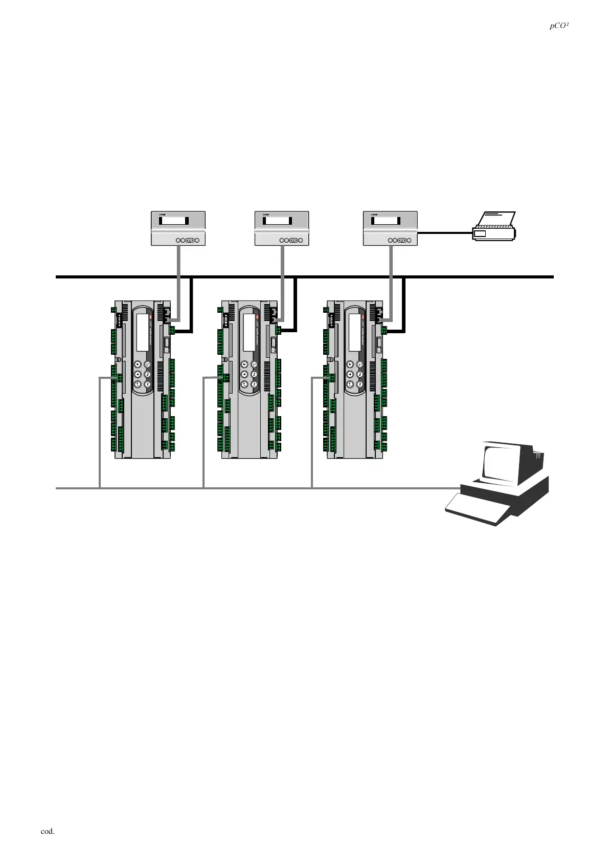
Generally, the application program can monitor the status of the network and intervene as a consequence to ensure the continuity
of the control functions.
The figure below, 5.1, shows the network connection diagram: DPD[LPXPRIXQLWVFDQEHFRQQHFWHG(including I/O interface
cards and user interface cards). The 32
nd
unit can only be a terminal.
on/off
enteralarm
pLAN (RS485 62.5kbit)
to a supervisory computer
supervisor network (RS485 up to 19.2kbit)
pCO² 3pCO² 4pCO² n
Terminal 1 Printer
on/off
enteralarm
Terminal 2
on/off
enteralarm
)LJ
All the versions of the pCO
2
can be connected in a local pLAN network without requiring additional boards.
The programs written for the different applications (e.g.: standard chiller, standard air-conditioners, compressor packs, ...) can
not be automatically integrated into a local network: they must be modified to consider the network strategy and structure, and
then be recompiled with the Easy-Tools system.
All the devices connected to the pLAN network are identified using their own individual address,IWKHVDPHDGGUHVVLV
DVVLJQHGWRPRUHWKDQRQHXQLWWKHQHWZRUNZLOOQRWZRUN. As the terminals and the pCO
2
I/O boards use the same type of
address, terminals and pCO
2
boards can not have the same identifier. The values which can be selected for the address range
from 1 to 32 for the terminals and from 1 to 31 for the I/O boards.
The addresses are set for the terminals using the dip-switches on the rear, and on the pCO
2
boards using the dip-switches located
near the telephone connector.
The network can be composed of each type of terminals LED, LCD 4x20 and graphic, as well as pCO and pCO
2
controls.
 Loading...


