Una possibile architettura hardware è così definita:
1. terminale utente con tastiera, display e LED di segnalazione;
2. pCO
2
(versione SMALL);
3. pCO
2
(versione LARGE);
4. cavo di collegamento tra terminale e pCO
2
;
5. cavo di collegamento tra terminale e stampante seriale (a cura del
cliente);
6. stampante seriale (a cura del cliente);
7. cavo AWG20/22 per connessione in pLAN tra più schede pCO
2
;
8. kit morsetti di connessione (in questo caso sconnessi dalla scheda
per renderli completamente visibili);
9. connessione ai sistemi di supervisione;
10.connessione alle espansioni I/O (solo vers. LARGE).
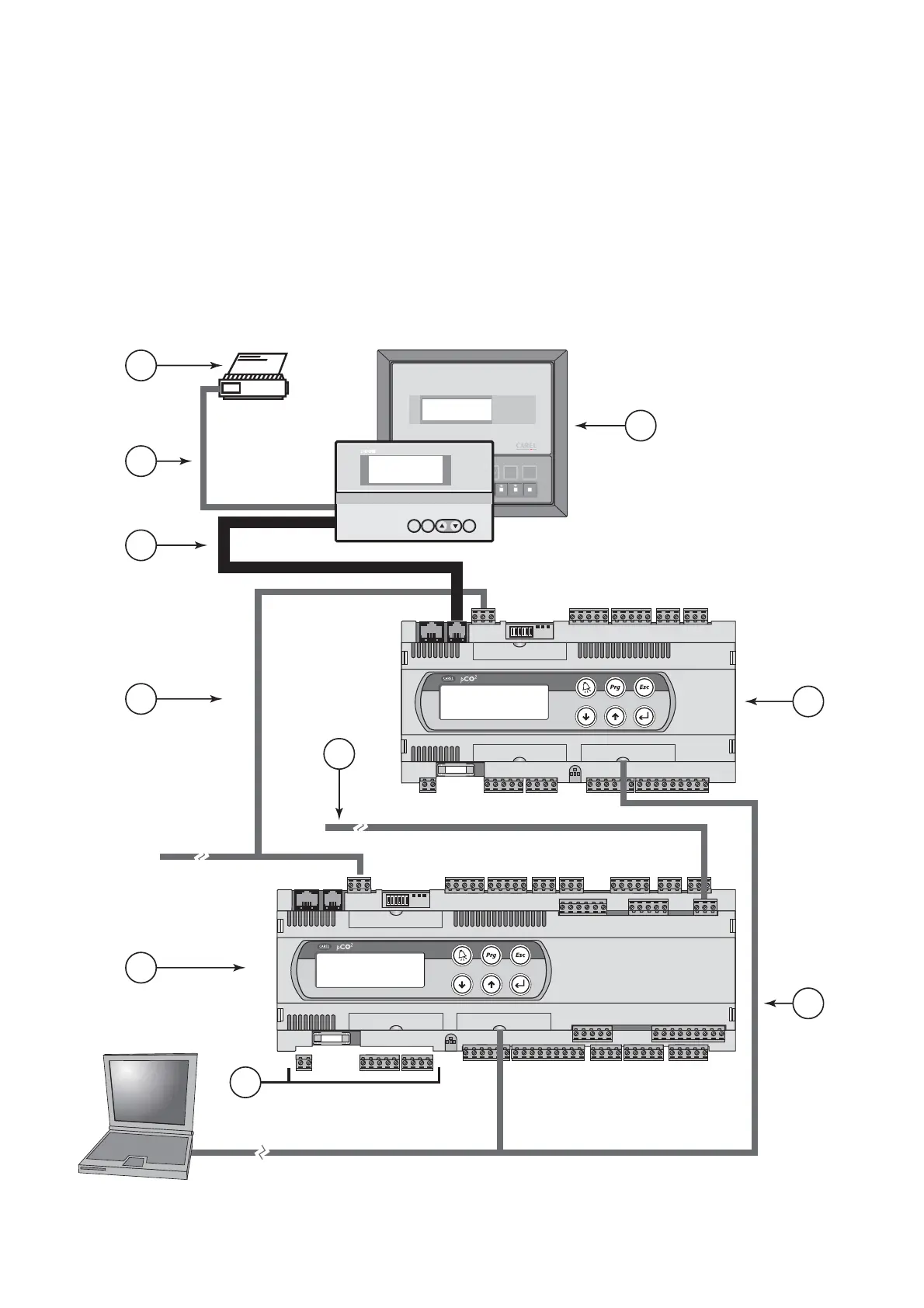
The hardware structure is defined as follows:
1. user terminal with keypad, display and LED signals;
2. pCO
2
(SMALL version);
3. pCO
2
(LARGE version);
4. connecting cable between terminal and pCO
2
;
5. connecting cable between terminal and serial printer (provided by
customer);
6. serial printer (provided by customer);
7. AWG20/22 cable for pLAN connection between a series of pCO
2
boards;
8. connection terminal kit (in this case disconnected from the board to
make them completely visible);
9. connection to supervisory systems;
10. connection to I/O expansions (LARGE version only).
10
pCO
2
- cod. +030221835 rel. 3.0 - 18.02.03

 Loading...


