pCO Sistema
Code: +030220336 - rel. 1.5 - 22/12/10
19
2.5 pCO
xs
board
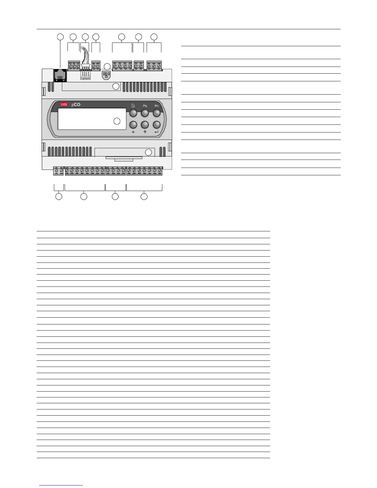
Key:
Key:Key:
Key:
1 Power supply connector [G (+), G0 (-)], 24 Vac or 24 to 48 Vdc;
2 Input (24 Vac) for phase control and NTC, 0/1 V, 0/5 V, 0/20 mA, 4/20 mA
analogue inputs, +5Vref for power supply to 5V ratiometric probe and
+24 Vdc power to active probes;
3 0 to 10 V analogue outputs and PWM output;
4 Digital inputs with voltage-free contact;
5 Connector for all standard pCO* series terminals and for downloading the
application program;
6 pLAN network connector;
7 tLAN terminal connector;
8 tLAN or MP-Bus network connector;
9 Relay digital outputs with one common;
10 Relay/SSR digital output;
11 Digital output for alarm relay with changeover contact/SSR;
12 Yellow power LED and 3 status LEDs
(see paragraph 6.3)
13 Cover for inserting the supervisor and telemaintenance option
14 Cover for inserting the clock board;
15 Built-In terminal.
Fig. 2.f
Fig. 2.fFig. 2.f
Fig. 2.f
2.5.1
2.5.12.5.1
2.5.1 Meaning of the pCO
Meaning of the pCOMeaning of the pCO
Meaning of the pCO
xs
xsxs
xs
board inputs/outputs
board inputs/outputsboard inputs/outputs
board inputs/outputs
Connector
Connector Connector
Connector
Signal
Signal Signal
Signal
Description
DescriptionDescription
Description
J1-1 G 24 Vac or 24 to 48 Vdc power supply
J1-2 G0 power supply reference
J2-1 SYNC synchronicity input for phase control (G0 is the reference)
J2-2 B1 universal analogue input 1 (NTC, 0/1V, 0/5 V, 0/20 mA, 4/20 mA)
J2-3 B2 universal analogue input 2 (NTC, 0/1V, 0/5 V, 0/20 mA, 4/20 mA)
J2-4 B3 universal analogue input 3 (NTC, 0/5 V)
J2-5 B4 universal analogue input 4 (NTC, 0/5 V)
J2-6 GND reference for the analogue inputs
J2-7 +5VREF power supply for 0/5 V ratiometric probes
J2-8 +24VDC 24 Vdc power supply for active probes
J3-1 Y1 analogue output no. 1, 0/10 V
J3-2 Y2 analogue output no. 2, 0/10 V
J3-3 Y3 analogue output no. 3, PWM (for phase cutting speed controllers)
J3-4 GND reference for analogue output
J4-1 ID1 digital input no. 1
J4-2 ID2 digital input no. 2
J4-3 ID3 digital input no. 3
J4-4 ID4 digital input no. 4
J4-5 ID5 digital input no. 5
J4-6 ID6 digital input no. 6
J4-7 IDC1 common for digital inputs from 1 to 6
J5 6-pin telephone connector for connection to the standard user terminal
J6-1 RX-/TX- RX-/TX- connector for RS485 connection to the pLAN network
J6-2 RX+/TX+ RX+/TX+ connector for RS485 connection to the pLAN network
J6-3 GND reference for RS485 connection to the pLAN network
J7 tLAN terminal connector
J8-1 TLAN connector to the tLAN network
J8-2 GND reference for connection to the tLAN network
J9-1 C1 common for relays: 1, 2, 3
J9-2 NO1 normally open contact, relay no. 1
J9-3 NO2 normally open contact, relay no. 2
J9-4 NO3 normally open contact, relay no. 3
J10-1 C4 common for relays: 4
J10-2 NO4 normally open contact, relay no. 4
J11-1 NO5 normally open contact, relay no. 5
J11-2 C5 common for relays: 5
J11-3 NC5 normally closed contact, relay no. 5
Tab. 2.e
Tab. 2.eTab. 2.e
Tab. 2.e
G
G0
SYNC
B1
B2
B3
B4
GND
+5VREF
+24VDC
Y1
Y2
Y3
GND
ID1
ID2
ID3
ID4
ID5
ID6
IDC1
RXTX-
RXTX+
GND
TLAN
GND
C1
NO1
NO2
NO3
C4
NO4
NO5
C5
NC5
J1
J5
J6
J7
J8
J9
J10
J11
J2
J3
J4
CLOCKCARD
SERIALCARD
13
1
12
14
5 6 7 8 9 10 11
3 42
built-in terminal
xs
15
 Loading...


