pCO Sistema
Code: +030220336 - rel. 1.5 - 22/12/10
48
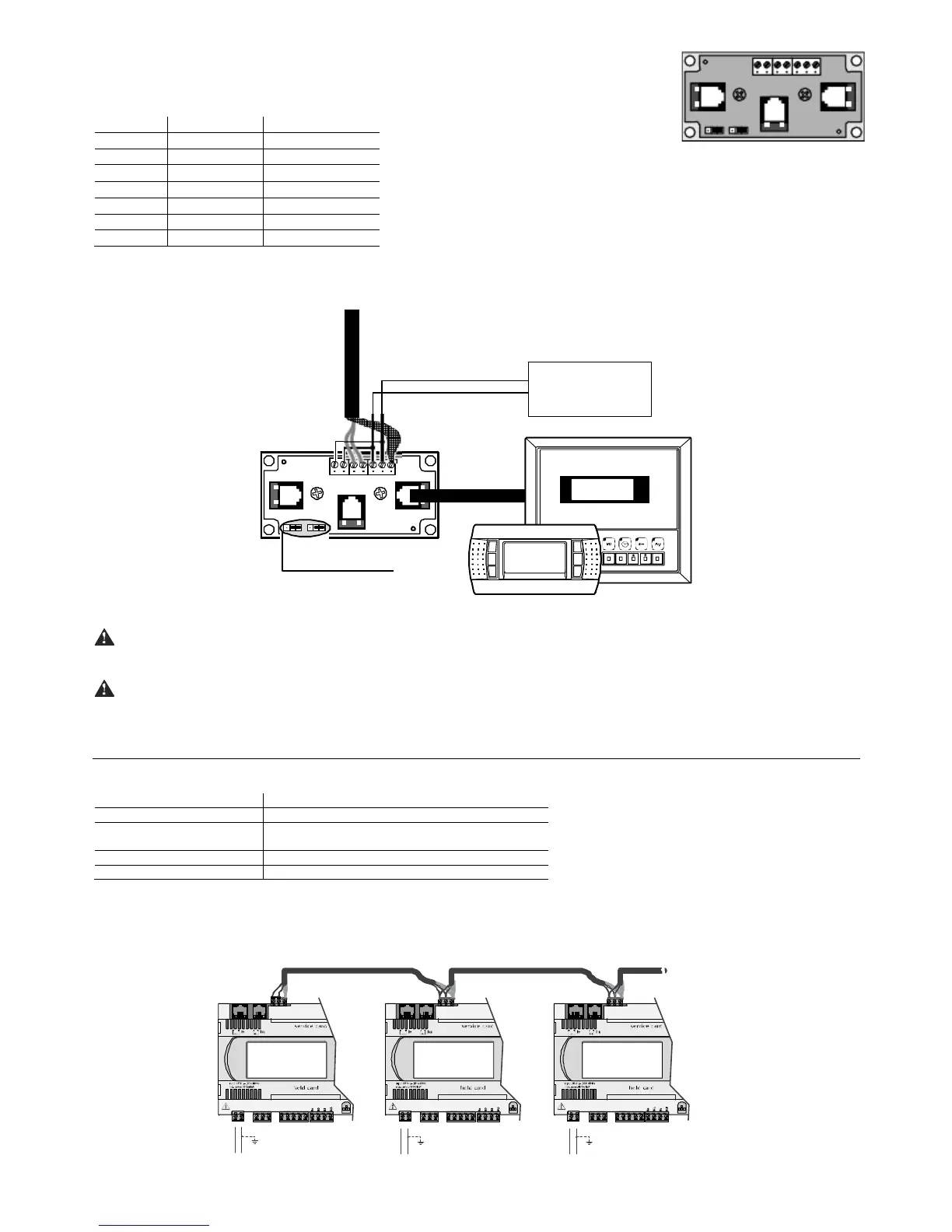
The Fig. 5.i represents the shunt code TCONN6J000, used in pairs for the remote installation of the pCO
in the pLAN network
with AWG20/22 shielded cable.
C
CC
Cable AWG20/22 (with power supply)
able AWG20/22 (with power supply)able AWG20/22 (with power supply)
able AWG20/22 (with power supply)
Terminal
TerminalTerminal
Terminal
Function
FunctionFunction
Function
Cable connections
Cable connectionsCable connections
Cable connections
0 Earth Shield
1 +VRL (H30 Vdc) First pair A
2 GND Second pair A
3 Rx/Tx- Third pair A
4 Rx/Tx+ Third pair B
5 GND Second pair B
6 +VRL (H30 Vdc) First pair B
Tab. 5.b
Tab. 5.bTab. 5.b
Tab. 5.b
5.7.1
5.7.15.7.1
5.7.1 Remote
Remote Remote
Remote installation of the terminal up to 500 m in pLAN network with AWG20/22 shielded cable
installation of the terminal up to 500 m in pLAN network with AWG20/22 shielded cableinstallation of the terminal up to 500 m in pLAN network with AWG20/22 shielded cable
installation of the terminal up to 500 m in pLAN network with AWG20/22 shielded cable
This installation is shown in Fig. 5.l. It requires a separate power supply via TCONN6J000.
J14 and J15 on 2-3
pLAN - to pCO
AWG20/22
1 twisted pair
+
-
on/offalar m enter
menu I/ O set prog.
?
info
Graphic
6 5 4 3 2 1 0
solo TCONN6J000
alimentatore
power supply
20...30 Vdc -150 mA
Fig. 5.u
Fig. 5.uFig. 5.u
Fig. 5.u
Important:
Important:Important:
Important: the overall length of the network must not exceed 500 m. Consequently if the terminal is also remote the length of the cable to the terminal is
included in the calculation of the total length.
The terminal
The terminalThe terminal
The terminal cable
cable cable
cable represents a branch of the network, and therefore if this is greater than 5 m in length it can only be connected to the first or the last pCO in
the network.
5.8 pLAN network technical specifications
The technical specifications of the pLAN network are summarised in the following table:
5.8.1
5.8.15.8.1
5.8.1 Optically
OpticallyOptically
Optically-
--
-isolated pLAN (pCO
isolated pLAN (pCOisolated pLAN (pCO
isolated pLAN (pCO
3
3 3
3
only)
only)only)
only)
The pCO
3
is also available with an optically-isolated serial pLAN. This simplifies installation, as the earthing requirements of the pCO
3
do not need to be observed. The
pCO
3
controllers can be connected to earth points with different voltages without the shield carrying current.
G
G0
RX- /TX+
RX+/TX-
GN D
G
G0
RX- /TX+
RX+/TX-
GN D
G
G0
RX- /TX+
RX+/TX-
GN D
AWG 20/22 AWG 20/22 AWG 20/22
Fig. 5.v
Fig. 5.vFig. 5.v
Fig. 5.v
6 5 4 3 2 1 0
 Loading...


