pCO Sistema
Code: +030220336 - rel. 1.5 - 22/12/10
42
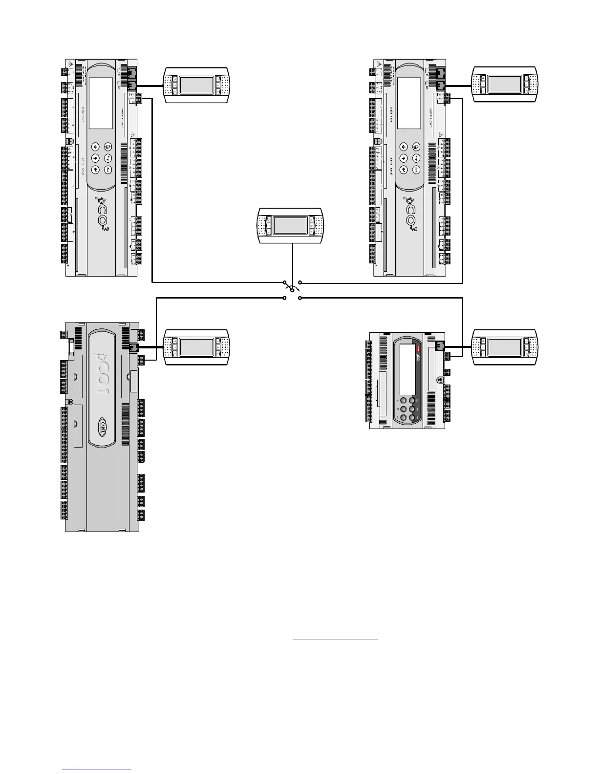
From the logical point of view, the connections are shown in the following figure:
Fuse
Program ming Ke y
1 2
4 3
pCO
XS
3
Private
pCO
1
4
Private
pCO
3
2
Private
pCO
3
1
Private
Shared
CLOCK C ARD
SERIAL CARD
built-in ter minal
x s
Fig. 5.b
Fig. 5.bFig. 5.b
Fig. 5.b
In the example, the shared terminal is associated with 4 pCO
C
controllers, however currently only controller 1 can display data and receive commands from the keypad.
The terminal is switched between the different controllers cyclically (1→2→3→4→1 …) by pressing a predefined button. Switching can also occur automatically,
managed directly by the program; in this case, in fact, a pCO controller can request control over the shared terminal to display new alarms or, vice-versa, give up
control to the next pCO after a preset time (cyclical rotation).
The data corresponding to the number and type of terminals are established during the initial configuration of the network, and are saved in the permanent memory
on each individual pCO controller. The details of the configuration are described below. The pLAN connection between two pCO controllers can only be made using
an AWG20/22 shielded cable, made up of a twisted pair plus the shield. The terminal and the pCO can be connected using a 6-wire telephone cable or AWG20/22
shielded cable, depending on the model of terminal.
Further details on the installation of the terminals are provided in the section on “pLAN electrical connections
pLAN electrical connectionspLAN electrical connections
pLAN electrical connections”.
 Loading...


