CAREL Industries HQs
Via dell’Industria, 11 - 35020 Brugine - Padova (Italy)
Tel. (+39) 0499716611 – Fax (+39) 0499716600 – www.carel.com – e-mail: carel@carel.com
Alimentazione /
Power supply
Alimentatore a bassissima tensione di sicurezza/sorgente di potenza
limitata /
Extra low voltage power supply / Limited power source.
+24 V
0V
+24 V
0V
Fig.5
Non aprire l’involucro dei pannelli quando sono alimentati /
Don’t open the
panel rear cover when the power supply is applied.
+24 V
0V
connettere a terra con un faston
L
N
N
L
+V
-V
100-240 Vac
PGTA00TRF0
PGD10/PGD13
Rear panel
Fig.6
Verifi care che l’alimentatore sia in grado di erogare la potenza necessaria per il
corretto funzionamento dell’apparecchiatura. E’ possibile ordinare l’alimentatore
230Vac/24Vdc - codice PGTA00TRF0. /
Ensure that the power supply has enough
power capacity for the operation of the devices
.
The 230 Vac/24Vdc power
supply - code PGTA00TRF0 can be ordered.
Collegamenti seriali /
Serial conncetions
PLC PORT: Com 1 - PC/PRINTER PORT: Com2
Fig. 7
Pin Description
1 GND
2-
3 TX/CHA-
4 RX/CHB-
5-
6 +5 V output
7 CTS/CHB+
8 RTS/CHA+
9
-
Per eff ettuare il collegamento con gli strumenti Carel in RS485 utilizzare l’apposito
cavo adattatore PGTA00CNV0. /
To make the RS485 connection to Carel
instruments use the special adapter cable code PGTA00CNV0.
Caratteristiche PGTA00CNV0
PGTA00CNV0
Technical specifi cations
lunghezza: 2 m
lenght
: 2 m
Il cavo è dotato di connettore
DB9 maschio e resistenze interne
di polarizzazione linea
The cable is fi tted with a DB9 male
connector and internal resistance
for line polarisation
terminazioni: Db9 maschio e
fi li sguainati con occhiello per
collegamento a terra della calza
terminations: DB9 male and stripped
wires with eyelet for earthing
the shield
Per il collegamento al pCO seguire i colori indicati in fi gura:
To connect the pCO follow the colours indicated in the fi gure:
GND
+
giallo / verde / marrone /
yellow / green / brown
grigio /
grey
nero /
black
collegare a terra /
connect to earth
Fig. 8
Regole per lo smaltimento /
Guidelines for disposal
• Non smaltire il prodotto come rifi uto solido urbano ma smaltirlo negli
appositi centri di raccolta.
• Il prodotto contiene una batteria ed è quindi necessario rimuoverla
separandola dal resto del prodotto seguendo le istruzioni riportate di seguito
prima di procedere al suo smaltimento.
• Un uso improprio o uno smaltimento non corretto potrebbe avere eff etti
negativi sulla salute umana e sull’ambiente.
• Per lo smaltimento vanno utilizzati i sistemi di raccolta pubblici o privati
previsti dalle leggi locali.
• In caso di smaltimento abusivo dei rifi uti elettrici ed elettronici sono previste
sanzioni stabilite dalle vigenti normative locali in materia di smaltimento.
•
Do not dispose of the product as municipal waste; it must be disposed of
through specialist waste disposal centres.
•
The product contains a battery that must be removed and separated from the
rest of the product according to the instructions provided, before disposing
of the product.
•
Improper use or incorrect disposal of the product may negative eff ects on
human health and on the environment.
•
The public or private waste collection systems defi ned by local legislation
must be used for disposal.
•
In the event of illegal disposal of electrical and electronic waste, the penalties
are specifi ed by local waste disposal legislation.
Battery
Fig. 9
Caratteristiche tecniche
pGD10” pGD13”
Display
Tipo TFT
Resoluzione 800x600, SVGA 1280x800, WXGA
Area display attiva 10.4” diagonal 13”3 diagonal
Colori 64 K
Retro-illuminazione LED
Luminosità 300 Cd/m
2
typ.
Regolazione luminosità Si
Requisiti di sistema
Sistema operativo Microsoft Windows CE 6.0
Memoria utente 256 MB Flash
RAM CPU 512 MB DDR
Interfaccia operativa
Touchscreen Analog resistive
Indicatori LED utente 1 (dual core)
Interfacce
Porta Ethernet 2 10/100 Mbit with intergrated switch
Porta USB Host interface, (1 vers. 2.0, 1 vers. 2.0 e 1.1)
Porta Seriale 1: Com1 RS232, RS485, RS422, confi gurabile via software
Memory card SD Card Slot
Funzionalità
Grafi ca vettoriale Si, incluso supporto SVG 1.0
Oggetti dinamici
Si. Visibilità, opacità, posizione, dimensione,
rotazione per molti tipi di oggetti
Font-TrueType Si
Multi-Protocollo Sì, massimo 2 driver
Storico e trend Si. Limitato alla memoria della Flash memory
Multi-lingue
Si, con impostazione della lingua run-timee
limitato solo dalla memoria disponibile
Recipes (ricette) Si. Limitato alla memoria della Flash memory
Allarmi Si
Lista eventi Si
Passwords Si
Hardware Real Time Clock Si, con batteria di back-up
Screen saver Sì
Buzzer “Beep” alla pressione del touch (confi gurabile)
Ratings
Alimentazione 24 Vdc (18...30 Vdc)
Corrente assorbita 0,95 A a 24 Vdc (max.) 1,15 A a 24 Vdc (max.)
Fusibile Automatico
Peso appross. 2,1 kg appross. 2,8 kg
Batteria Ricaricabile a litio, non sostituibile dall’utente
Condizioni ambientali
Temperatura di lavoro 0...50 °C (installazione verticale)
Temperatura di
immagazzinamento
-20...70 °C
Umidità i lavoro e
immagazzinamento
5 – 85 % umidità relativa, non-condensante
Grado di protezione IP65 (front panel) - IP20 (rear)
Dimensioni
Pannello frontale LxH
287x232 mm 337x267 mm
(13.22x10.51“)
Foratura AxB
276x221 mm 326x256 mm
(12.83x10.07“)
Profondità D+T 56mm + 4mm 56+4 mm (2.20+0.16”)
L’utilizzo di queste apparecchiature in ambienti residenziali, commerciali
e dell’industria leggera è permesso solo nel caso in cui vengano prese
le misure speciali per ottenere la conformità alla IEC61000-6-3.
CAREL si riserva la possibilità di apportare modifi che o cambiamenti ai propri
prodotti senza alcun preavviso.
Smaltimento del prodotto: l’apparecchiatura (o il prodotto) deve essere oggetto di
raccolta separata in conformità alle vigenti normative locali in materia di smaltimento. /
Disposal of the product: the appliance (or the product) must be disposed of separately in
accordance with the local waste disposal legislation in force.
+050001485 - rel. 1.3 date 27.01.2016
Technical Specifi cation
pGD10” pGD13”
Display
Type TFT
Resolution 800x600, SVGA 1280x800, WXGA
Active display area 10.4” diagonal 13”3 diagonal
Colours 64 K
Backlight LED
Brightness 300 Cd/m
2
typ.
Dimming Yes
System resources
Operating System Microsoft Windows CE 6.0
User memory 256 MB Flash
RAM CPU 512 MB DDR
Operator Interface
Touchscreen Analogue resistive
User LED indicators 1 (dual core)
Interfaces
Ethernet port 2 10/100 Mbit with intergrated switch
USB port Host interface, (1 vers. 2.0, 1 vers. 2.0 e 1.1)
Serial Port 1: Com1 RS232, RS485, RS422, software confi gurable
Memory card SD Card Slot
Functions and features
Vector graphics Yes, includes SVG 1.0 support
Object dynamics
Yes. Visibility, opacity, position size,
rotation for object types.
TrueType fonts Yes
Multiple driver commun. Yes, max 2 drivers
Data acquisition
and trend presentation
Yes. Flash memory storage limited only
by available memory
Multilanguage
Yes, number of run-time languages limited
by available memory
Recipes Yes. Flash memory storage limited by available mem.
Alarms Yes
Event list Yes
Passwords Yes
Hardware Real Time Clock Yes, with battery back-up
Screen saver Yes
Buzzer Yes, audible feedback for touchscreen
Ratings
Power supply voltage 24 Vdc (18 to 30 Vdc)
Current consumption 0,95 A a 24 Vdc (max.) 1.15 A a 24 Vdc (max.)
Fuse Automatic
Weight Approx 2.1 kg Approx 2.8 kg
Battery Rechargeable Lithium battery, not user-replaceable
Environmental conditions
Operating temperature 0...50 °C (vertical installation)
Storage temperature -20...70 °C
Operating and storage
humidity
5 – 85 % relative humidity, non-condensing
Protection class IP65 (front panel) - IP20 (rear)
Dimensions
Faceplate LxH
287x232 mm 337x267 mm
(13.22x10.51“)
Cutout AxB
276x221 mm 326x256 mm
(12.83x10.07“)
Depth D+T 56mm + 4mm 56+4 mm (2.20+0.16”)
These devices may only be used in residential, commercial and
light industrial environments if special measures are taken to ensure
conformity to IEC61000-6-3.
CAREL reserves the right to modify the features of its products without prior notice.
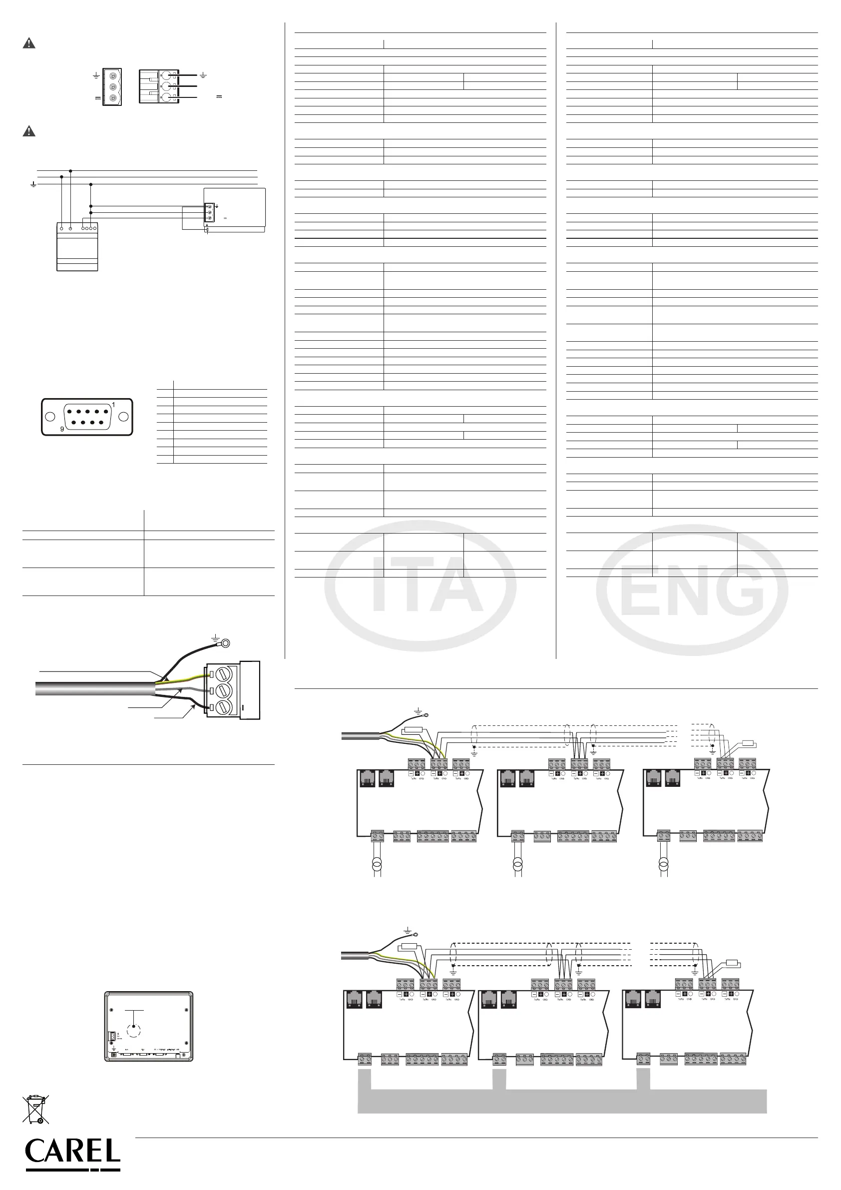
Schema per collegamento a pCO
5
/
Connection to pCO
5
R = 120 ohm
230 Vac
24 Vac
L
N
230 Vac
24 Vac
L
N
230 Vac
24 Vac
L
N
J26FBus2
J25 BMS2
J11 pLAN
pCO5
G
G0
J26FBus2
J25 BMS2
J11 pLAN
pCO5
G
G0
J26FBus2
J25 BMS2
J11 pLAN
pCO5
G
G0
R=120 ohm
collegare a terra /
connect to earth
Fig. 10
R = 120 ohm
R = 120 ohm
J26FBus2
J25 BMS2
J11 pLAN
pCO5
G
G0
J26FBus2
J25 BMS2
J11 pLAN
pCO5
G
G0
J26FBus2
J25 BMS2
J11 pLAN
pCO5
G
G0
Power
supply
collegare a terra /
connect to earth
Fig. 11
 Loading...