+0500090ML - rel. 1.3 - 20.05.2020
Codici opzioni
CODICE DESCRIZIONE CODICE DESCRIZIONE
IROPZDSP00 interfaccia display remoto IROPZKEY00 chiave di program. parametri memoria estesa con batterie 12 V
IR00XGD000 display ripetitore remoto PSTCON0*B0 cavi di conness. display ripetitore (*: 1= 1,5 m; 3= 3 m; 5= 5m)
IROPZ485S0 interf. RS485 scheda seriale con riconoscimento automatico della polarità +/-
Come impostare il set point
Step Azione Eetto Signicato
1
Premere per 1 sec il tasto
Dopo 1 secondo il display visualizzerà
il valore attuale del setpoint
E’ il setpoint di regolazione al momento
attivo
2
Premere il tasto
o
Il valore sul display aumenterà o diminuirà Impostare il valore desiderato
3
Premere il tasto
Il controllore visualizzerà nuovamente la
temperatura letta dalle sonde
Il set point è modicato e salvato
Un altro modo di cambiare il setpoint è modicare il parametro “St” (vedi tabelle successive)
Come accedere e modicare i parametri: tipo “F” (FREQUENTI, non protetti da password) - tipo “C”
(CONFIGURAZIONE, protetti da password)
Step Azione Eetto Signicato
1
Premere per 3 sec il tasto
Dopo 3 secondi il display visualizzerà il
primo parametro, “0” (Password)
L’accesso ai parametri tipo “F” è diretto
senza password.
2
Premere il tasto
o
Il valore sul display aumenterà o diminuirà
Inserire la password “22” per accedere
ai parametri tipo “C”, o qualsiasi altro
valore per gli “F”
3
Premere il tasto
Il display visualizzerà “St” (Stepoint) E’ il valore attuale del Setpoint
4
Premere il tasto
o
Il display scorrerà la lista dei parametri tipo
“C” se avete impostato la password =22 o
tipo “F” in caso contrario
Selezionare il parametro desiderato
5
Premere il tasto
Il display visualizzerà il valore del parametro
selezionato
E’ il valore attuale del parametro
6
Premere il tasto
o
Il valore sul display aumenterà o diminuirà Impostare il valore desiderato
7
Premere il tasto
Il display tornerà a visualizzare il nome del
parametro
ATTENZIONE: l’aggiornamento dei
parametri non è ancora attivo
8
Ripetere gli step 4, 5, 6 e 7 per tutti i
parametri richiesti
9
Premere per 5 s il tasto
Il controllore visualizzerà nuovamente la
temp. letta dalle sonde
ATTENZIONE: solo ora tutti i parametri
saranno aggiornati
Per entrambi gli accessi (parametri tipo “F” e tipo “C”) è prevista un’uscita automatica per time-out (dopo 1 min in cui non viene
premuto alcun tasto della tastiera), che non aggiorna i parametri.
Accesso ai parametri suddivisi per blocchi funzionali (permette all’utente di scorrere la lista parametri a blocchi)
Una volta ottenuto l’accesso ai parametri di tipo “F” o “C” (vedi tabelle precedenti)
Step Azione Eetto Signicato
1
Premere il tasto
Il display visualizzerà il nome del blocco
funzionale a cui appartiene il parametro
Es.: ‘CMP’ per i parametri riguardanti il compressore,
‘dEF’ per i parametri riguardanti il sbrinamento
2
Premere il tasto
o
Il display visualizzerà il nome degli altri
blocchi funzionali
Esempio ‘Fan’ per i parametri riguardanti i
ventilatori
3
Premere il tasto
Il display visualizzerà il nome del primo pa-
rametro del blocco funzionale selezionato
Esempio “F0” per ‘Fan’
Ripristino allarmi a reset manuale
È possibile resettare tutti gli allarmi a ripristino manuale premendo insieme i tasti e per più di
3 s.
Sbrinamento manuale
Oltre allo sbrinamento automatico è possibile attivare uno sbrinamento manuale, se esistono le condizioni di temperatura, premendo
il tasto
per 5 s.
Ciclo continuo
Per attivare la funzione di ciclo continuo premere contemporaneamente i tasti e per più di 3 s. Durante tutto il funzionamen-
to in ciclo continuo, il compressore continuerà a funzionare e si fermerà per time-out ciclo o per raggiungimento della temperatura
minima prevista (AL = soglia di allarme di minima temperatura).
Settaggio ciclo continuo: parametro “cc” (durata ciclo continuo): “cc”= 0 mai attivo; parametro “c6” (esclusione allarme dopo ciclo
continuo): esclude o ritarda l’allarme di bassa al termine del ciclo continuo.
Procedura di impostazione dei parametri di default
Per impostare i parametri di default del controllo si procede in questo modo:
• Se “Hdn” = 0:
1: togliere tensione allo strumento;
2: ridare tensione allo strumento tenendo premuto il tasto
no alla comparsa del messaggio “Std” sul display.
NOTA: i valori di default vengono impostati solo per i parametri visibili (C e F). Per maggiori dettagli vedere la tabella Riepilogo
parametri di funzionamento.
• Se “Hdn” < > 0:
1: togliere tensione allo strumento;
2: ridare tensione allo strumento tenendo premuto il tasto
no alla comparsa del valore bn0;
3: selezionare il set di parametri di Default, tra 0 e “Hdn” che si vuole impostare per mezzo dei tasti
o ;
4: premere il tasto
no alla comparsa del messaggio “Std” sul display.
Funzione HACCP
SmartCella è conforme alle normative HACCP in quanto permette il monitoraggio della temperatura del cibo conservato.
Allarme “HA”= superamento soglia massima: vengono memorizzati no a tre eventi HA (HA, HA1, HA2) rispettivamente dal più
recente (HA) al più vecchio (HA2) e una segnalazione HAn che visualizza il numero di eventi HA intervenuti.
Allarme “HF”= mancata tensione per più di 1 minuto e superamento soglia massima AH: vengono memorizzati no a tre eventi HF
(HF, HF1, HF2) rispettivamente dal più
recente (HF) al più vecchio (HF2) e una segnalazione HFn che visualizza il numero di eventi HF intervenuti.
Settaggio allarme HA/HF: parametro AH (soglia di alta temp.); Ad e Htd (Ad + Htd = ritardo allarme HACCP).
Visualizzazione dei dettagli: premere il tasto
per accedere ai parametri HA o HF e scorrere con i tasti o .
Cancellazione allarmi HACCP: premere in qualsiasi momento per 5 s dall’interno del menù il tasto
e , un messaggio “res”
indicherà l’avvenuta cancellazione dell’allarme attivo. Per cancellare anche gli allarmi memorizzati premere per 5 s la combinazione
di questi tre tasti:
+ + .
Tabella allarmi e segnalazioni: display, buzzer e relè
Codice Icona sul display Relè allar. Buzzer Ripristino Descrizione
‘rE’
+ lampeggiante
ON ON automatico sonda virtuale di regolazione guasta
‘E0’
+ lampeggiante
OFF OFF automatico sonda ambiente S1 guasta
‘E1’
+ lampeggiante
OFF OFF automatico sonda sbrinamento S2 guasta
‘E2’-3-4
+ lampeggiante
OFF OFF automatico sonda S3-4 guasta
‘___’ nessuna OFF OFF automatico sonda non abilitata
‘LO’
lampeggiante
ON ON automatico allarme bassa temperatura
‘HI’
lampeggiante
ON ON automatico allarme alta temperatura
‘A F r ’
lampeggiante
ON ON manuale allarme antigelo
‘IA’
lampeggiante
ON ON automatico allarme immediato da contatto esterno
‘d A’
lampeggiante
ON ON automatico allarme ritardato da contatto esterno
‘dEF’
acceso
OFF OFF automatico sbrinamento in esecuzione
‘Ed1’-2 nessuna OFF OFF autom. /man. sbrinamento su evaporatore 1-2 terminato per timeout
‘Pd’
+ lampeggiante
ON ON autom. /man. allarme tempo massimo di pump-down
‘LP’
+ lampeggiante
ON ON autom. /man. allarme di bassa pressione
‘AtS’
+ lampeggiante
ON ON autom. /man. autostart in pump-down
‘cht’ nessuna OFF OFF autom. /man. preallarme alta temperatura condensatore
‘CHT’
+ lampeggiante
ON ON manuale allarme alta temperatura condensatore
‘dor’
+ lampeggiante
ON ON automatico allarme porta aperta per troppo tempo
‘Etc’
lampeggiante OFF OFF autom. /man. real time clock guasto
‘EE’
+ lampeggiante
OFF OFF automatico Errore Eeprom parametri macchina
‘EF’
+ lampeggiante
OFF OFF automatico Errore Eeprom parametri di funzionamento
‘HA’
lampeggiante
OFF OFF manuale allarme HACCP di tipo ‘HA’ /
‘HF’
lampeggiante
OFF OFF manuale allarme HACCP di tipo ‘HF
‘ccb’ segnalazione Richiesta inizio ciclo continuo
‘ccE’ segnalazione Richiesta ne ciclo continuo
‘dFb’ segnalazione Richiesta inizio defrost
‘dFE’ segnalazione Richiesta ne defrost
‘On’ segnalazione Passaggio a stato di ON
‘OFF’ segnalazione Passaggio a stato di OFF
‘rES’ segnalazione Reset allarmi a ripristino manuale; Reset allarmi HACCP;
Reset monitoraggio temperatura
‘n1’...‘n6’
lampeggiante
ON ON automatico Indica allarme sull’unità 1...6 presente nella rete /
NOTA: Il buzzer viene attivato se abilitato dal parametro ‘H4’.
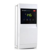
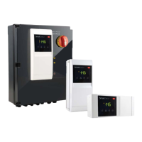
SmartCella - Controllo elettronico per celle frigorifere/Electronic controller for cold rooms
Option codes
CODE DESCRIPTION CODE DESCRIPTION
IROPZDSP00 remote display interface IROPZKEY00 parameter programming key, extended memory with 12 V batteries
IR00XGD000 remote repeater dispaly PSTCON0*B0 repeater display connection cables (*: 1= 1,5 m; 3= 3 m; 5= 5m)
IROPZ485S0 RS485 serial board interface with automatic recognition of the polarity +/-
How to set the set point (desired temperature value)
Step Action Eect Meaning
1
Press
for 1 second
After 1 second the display will show the
current set point
This the currently active control
set point
2
Press
or
The value on the display will increase or
decrease
Set the desired value
3
Press
The controller will show the temp.read by the
probes again
The set point is modied and saved
Another way of changing the set point is to set parameter “St” (see the tables below)
How to access and set parameters: type “F” (FREQUENT, not protected by password); type “C” (CONFIGU-
RATION, password protected)
Step Action Eect Meaning
1
Press
for 3 seconds
After 3 seconds the display will show the 1st
parameter, “0” (Password)
Access to type “F” parameters is direct
without password
2
Press
or
The value on the display will increase or decrease.
Enter the password “22” to access the
type “C” parameters or whatever die-
rent value for the type “F” parameters.
3
Press
The display will show “St” (Setpoint) This is the current value of the Setpoint
4
Press
or
If the password set is 22 the display will scroll the
list of type “C” parameters (CONFIGURATION) other-
wise the list of type “F” parameters (FREQUENT)
Set the desired value
5
Press
The display will show the parameter name
This is the current value of the
parameter
6
Press
or
The value on the display will increase or decrease Set the desired value
7
Press
The display will show the parameter name again IMPORTANT: parameters not yet saved
8
Repeat steps 2, 3, 4 & 5 for
all parameters required
9
Press
for 5 seconds
The controller will display the temperature read by
the probes again
IMPORTANT: only now have all the
parameters been updated
For both types of access (type “F” and type “C”) there is a timeout (no button on the keypad pressed for 1 min), the procedure is
ended without saving the parameter.
Accessing the parameters divided by functional blocks (allows the user to scroll the list of parameters in blocks)
Once having accessed the type “F” or “C” parameters (see tables above)
Step Action Eect Meaning
1
Press
The display will show the name of the functional
block that the parameter belongs to
Example ‘CMP’ for the compressor parameters,
‘dEF’ for the defrost parameters
2
Press
or
The display will show the name of the other
functional blocks
Example ‘Fan’ for the fan parameters
3
Press
The display will show the name of the rst
parameter in the functional block selected
Example “F0” for ‘Fan’
Alarms with manual reset
The alarms with manual reset can be reset by pressing the and for more than 3 s.
Manual defrost
As well as the automatic defrost function, a manual defrost can be enabled, if the temperature conditions allow, by pressing the
button for more than 5 s.
Continuous cycle
Pressing the buttons and simultaneously for more than 3 s enables the continuous cycle function. During operation in
continuous cycle, the compressor continues to operate for the time ‘cc’ and it stops when reaches the ‘cc’ time out or the minimum
temperature envisaged (AL = minimum temperature alarm threshold).
Continuous cycle setting: “cc” parameter (continuous cycle duration): “cc” = 0 never active; “c6” parameter (bypassing the alarm
after the continuous cycle): “cc” = 0 never active; it avoids or delays the low temperature alarm after the continuous cycle.
Procedure for setting the default parameter values
To set the default parameter values on the controller, proceed as follows:
• If “Hdn” = 0:
1: switch the instrument o;
2: switch the instrument back on, holding the
button until the message “Std” is shown on the display.
NOTE: the default values are only set for the visible parameters (C and F). For further details see table “Summary of operating
parameters”.
• If “Hdn” < > 0:
1: switch the instrument o;
2: switch the instrument back on, holding the
button until the value bn0 is shown on the display;
3: select the set of default parameters, between 0 and “Hdn”, using the and buttons;
4: press the
button until the message “Std” is shown on the display.
HACCP function
SmartCella is compliant with the HACCP standards in force since it allows the monitoring of the temperature of the stored food.
“HA” alarm = exceeded maximum threshold: up to three HA events are saved (HA, HA1, HA2) respectively from the more recent (HA)
to the oldest (HA2) and a HAn signal that displays the number of occurred HA events.
“HF” alarm = power failure lasting over a minute and exceeded AH maximum threshold: up to three HF events are saved (HF, HF1,
HF2) respectively from the more recent (HF) to the oldest (HF2) and a HFn signal that displays the number of occurred HF events.
HA/HF alarm setting: AH parameter (high temp. threshold); Ad and Htd (Ad+Htd = HACCP alarm activation delay).
Display of the details: access to HA or HF parameters pressing the
button and use or buttons to glance over.
HACCP alarm erasing: press the
and buttons for more than 5 seconds, the message ‘res’ indicates that the alarm have
been deleted. To cancel the saved alarms press the
+ + buttons for more than 5 seconds.
Table of alarms and signals: display, buzzer and relay
Code Icon on the display Alarm relay Buzzer Reset Description
‘rE’
+ ashing
ON ON automatic virtual control probe fault
‘E0’
+ ashing
OFF OFF automatic room probe S1 fault
‘E1’
+ ashing
OFF OFF automatic defrost probe S2 fault
‘E2’-3-4
+ ashing
OFF OFF automatic probe S3-4 fault
‘___’ no OFF OFF automatic probe not enabled
‘LO’
ashing
ON ON automatic low temperature alarm
‘HI’
ashing
ON ON automatic high temperature alarm
‘A F r ’
ashing
ON ON manual antifreeze alarm
‘IA’
ashing
ON ON automatic immediate alarm from external contact
‘d A’
ashing
ON ON automatic delayed alarm from external contact
‘dEF’
on
OFF OFF automatic defrost running
‘Ed1’-2 no OFF OFF autom./man. defrost on evaporator 1-2 ended by timeout
‘Pd’
+ ashing
ON ON autom./man. maximum time pump-down alarm
‘LP’
+ ashing
ON ON autom./man. low pressure alarm
‘AtS’
+ ashing
ON ON autom./man. autostart in pump-down
‘cht’ no OFF OFF autom./man. high condenser temperature pre-alarm
‘CHT’
+ ashing
ON ON manual high condenser temperature alarm
‘dor’
+ ashing
ON ON automatic door open for too long alarm
‘Etc’
ashing
OFF OFF autom./man. real time claock fault
‘EE’
+ ashing
OFF OFF automatic EEPROM error, unit parameters
‘EF’
+ ashing
OFF OFF automatic EEPROM error, operating parameters
‘HA’
ashing
OFF OFF manual HACCP alarm, type ‘HA’
‘HF’
ashing
OFF OFF manual HACCP alarm, type ‘HF’
‘ccb’ signal Request to start continuous cycle
‘ccE’ signal Request to end continuous cycle
‘dFb’ signal Request to start defrost
‘dFE’ signal Request to end defrost
‘On’ signal Switch ON
‘OFF’ signal Switch OFF
‘rES’ signal Reset alarms with manual reset; Reset HACCP alarms; Reset
temperature monitoring
‘n1’...‘n6’
ashing
ON ON automatic Indicates an alarm on unit 1 to 6 present in the network
NOTE: The buzzer is enabled if enabled by the parameter ‘H4
Codes des options
CODE DESCRIPTION CODE DESCRIPTION
IROPZDSP00 interface acheur déporté IROPZKEY00 clef de programmation paramètres, mémoire étendue avec batteries 12 V
IR00XGD000 acheur répétiteur déporté PSTCON0*B0 câbles de connexion acheur répétiteur (*: 1= 1,5 m; 3= 3 m; 5= 5m)
IROPZ485S0 carte interface RS485 avec reconaissance automatique de la polarité +/-
Comment congurer la valeur de consigne
Étape Action Eet Signication
1
Appuyer pendant 1 sec sur la touche
1 seconde après l'écran achera
la valeur actuelle de la valeur de consigne
C'est la valeur de consigne
active à ce moment-là
2
Appuyer sur la touche
ou
La valeur sur l'écran augmentera ou diminuera Congurer la valeur souhaitée
3
Appuyer sur la touche
Le contrôleur achera de nouveau la
température lue par les sondes
La valeur de consigne est
modiée et sauvegardée
L’autre manière de changer la valeur de consigne est de modier le paramètre “St” (voir tableaux suivants)
Comment accéder et modier les paramètres de type “F” (FRÉQUENTS, non protégés par mot de passe) -
de type “C” (CONFIGURATION, protégée par mot de passe)
Éta.
Action Eet Signication
1
Appuyer pendant 3 sec sur la touche
3 secondes après l’écran achera le
premier paramètre, “0” (mot de passe)
L’accès aux paramètres type “F”
est direct
2
Appuyer sur la touche
ou
La valeur sur l’écran augmentera ou
diminuera
Saisir le mot de passe “22” pour accéder
aux param. “C”, ou toute autre valeur
pour accéder aux paramètres “F”
3
Appuyer sur la touche
L’écran achera la valeur du “St” (Setpoint) C'est la valeur actuelle du par. Setpoint
4
Appuyer sur la touche
ou
Sur l’écran délera la liste des paramètres
type “C” (CONFIG.) cela dénissée le mot
de passe = 22 ou autrement de type “F“
Sélectionner le paramètre souhaité
5 Appuyer sur la touche SET L’écran achera la valeur du paramètre sélect. C’est la valeur actuelle du paramètre
6
Appuyer sur la touche
ou
La valeur sur l’écran augmentera ou
diminuera
Congurer la valeur souhaitée
7
Appuyer sur la touche
L'écran achera de nouveau le nom du
paramètre
ATTENTION: la mise à jour des
paramètres n'est pas encore active
8
Répéter les étapes 2, 3, 4 et 5 pour tous les
paramètres requis
7
Appuyer pendant 5 sec sur la touche
Le contrôleur achera de nouveau la
température lue par les sondes
ATT.: seulement maintenant tous les
paramètres seront mis à jour
Pour les deux accès (paramètres type “F” et type “C”) est prévue une sortie automatique pour time-out (après n’avoir appuyé sur
aucune touche pendant 1 min), qui ne met pas à jour les paramètres.
Accès aux paramètres divisés en blocs fonctionnels (cela permet à l’utilisateur de faire déler la liste des
paramètres par blocs)
Une fois obtenu l’accès aux paramètres de type “F” ou “C” (voir tableaux précédents)
Étape Action Eet Signication
1
Appuyer sur la touche
L'écran achera le nom du bloc
fonctionnel auquel appartient le
paramètre
Exemple “CMP” pour les paramètres
concernant le compresseur, “dEF” pour les
paramètres concernant le dégivrage
2
Appuyer sur la touche
ou
L'écran achera le nom des autres
blocs fonctionnels
Exemple ‘Fan’ pour les paramètres
concernant les ventilateurs
3
Appuyer sur la touche
L'écran achera le nom du premier
par. du bloc fonctionnel sélectionné
Exemple “F0” pour ‘Fan’
Réinitialisation des alarmes par remise à zéro manuelle
On peut remettre à 0 toutes les alarmes manuellement en appuyant en même temps sur les touches
et pendant plus de 3 s.
Dégivrage manuel
Outre le dégivrage automatique, on peut activer un dégivrage manuel si les conditions de températures sont favorables en appuyant
sur la touche
pendant 5 s.
Cycle continu
Pour activer la fonction de cycle continu, appuyer en même temps sur les touches
et pendant plus de 3 s. durant le
fonctionnement en cycle continu, le compresseur fonctionne pendant toute la durée prévue et il s’arrêtera en attente du cycle ou
parce que la température minimale prévue a été atteinte (AL = seuil d‘alarme de température minimale).
Réglage du cycle continu: paramètre “cc” (durée du cycle continu): “cc”= 0 jamais actif; paramètre “c6” (exclusion de l’alarme après
un cycle continu). exclut ou retarde l’alarme de basse température à la n du cycle continu.
Procédure de programmation des paramètres de défaut
Procéder de la façon suivante pour programmer les paramètres de défaut du contrôle:
• Si “Hdn” = 0:
1: couper la tension à l’instrument;
2: redonner de la tension à l’instrument en maintenant enfoncée la touche
jusqu’à ce que le message “Std” ne s’ache sur l’écran.
Remarque: les valeurs de défaut sont programmées seulement pour les paramètres visibles (C et F). Pour plus de détails, consulter le
tableau-résumé des paramètres de fonctionnement.
• Si “Hdn” < > 0:
1: couper la tension à l’instrument;
2: redonner de la tension à l’instrument en maintenant enfoncée la touche
jusqu’à ce que la valeur bn0 ne s’ache;
3: sélectionner le set de paramètres de Défaut, entre 0 et “Hdn” que l’on veut programmer à l’aide des touches
et ;
4: appuyer sur la touche
jusqu’à ce que le message “Std” ne s’ache sur l’écran.
Fonction HACCP
SmartCella est conforme aux réglementations HACCP étant donné qu’il permet la supervision de la température des aliments conservés.
Alarme “HA”= dépassement du seuil maximum: en outre, on peut mémoriser jusqu’à trois évènements HA (HA, HA1, HA2) respecti-
vement du plus récent (HA) au plus ancien (HA2) ainsi qu’une signalisation HAn qui ache le nombre d’évènements HA intervenus.
Alarme “HF”= manque tension pendant plus d’1 minute et dépassement du seuil maximum AH: en outre, on peut mémoriser
jusqu’à trois évènements HF (HF, HF1, HF2) respectivement du plus récent (HF) au plus ancien (HF2) et ainsi qu’une signalisation HFn
qui ache le nombre d’évènements HF intervenus.
Programmation de l’alarme HA/HF: paramètre AH (seuil de température élevée); Ad et Htd (Ad + Htd = retard alarme HACCP).
Achage des détails: appuyer sur la touche
pour accéder aux paramètres HA ou HF et faire déler avec les touches ou
Eacement des alarmes HACCP: appuyer sur les touches et à l’intérieur du menu et à n’importe quel moment pendant
plus de 5 s, un message “res” indiquera l’eacement eectif de l’alarme active. Pour eacer les alarmes mémorisées également,
appuyer sur ces trois touches:
+ + pendant plus de 5 s.
Table des alarmes et signaux: écran, buzzer et relais
Code Icon on the display Alarm relay Buzzer Reset Description
‘rE’
+ clignotant
ON ON Automatique panne de sonde de commande virtuelle
‘E0’
+ clignotant
OFF OFF Automatique panne sonde ambiante S1
‘E1’
+ clignotant
OFF OFF Automatique panne sonde de dégivrage S2
‘E2’-3-4
+ clignotant
OFF OFF Automatique panne sonde S3-4
‘___’ Aucun OFF OFF Automatique sonde non activée
‘LO’
clignotant
ON ON Automatique alarme basse température
‘HI’
clignotant
ON ON Automatique alarme haute température
‘A F r ’
clignotant
ON ON Manuel alarme antigelt
‘IA’
clignotant
ON ON Automatique alarme immédiate sur contact externe
‘d A’
clignotant
ON ON Automatique alarme retardée sur contact externe
‘dEF’
ON
OFF OFF Automatique dégivrage en cours
‘Ed1’-2 Aucun OFF OFF Autom. / Man. dégivrage sur évaporateur 1-2 terminé avant temporisation
‘Pd’
+ clignotant
ON ON Autom. / Man. alarme de pompage temps maximum
‘LP’
+ clignotant
ON ON Autom. / Man. alarme basse pression
‘AtS’
+ clignotant
ON ON Autom. / Man. auto-démarrage en pompage
‘cht’ Aucun OFF OFF Autom. / Man. pré-alarme température condensateur élevée
‘CHT’
+ clignotant
ON ON Manuel alarme température condensateur élevée
‘dor’
+ clignotant
ON ON Automatique alarme porte ouverte trop longtemps
‘Etc’
clignotant OFF OFF Autom. / Man. panne horloge en temps réel
‘EE’
+ clignotant
OFF OFF Automatique erreur EEPROM, paramètres unitaires
‘EF’
+ clignotant
OFF OFF Automatique erreur EEPROM, paramètres de fonctionnement
‘HA’
clignotant
OFF OFF Manuel alarme HACCP, type ‘HA’HA
‘HF’
clignotant
OFF OFF Manuel alarme HACCP, type ‘HF’
‘ccb’ signal Demande de démarrage d'un cycle continu
‘ccE’ signal Demande de n d'un cycle continu
‘dFb’ signal Demande de démarrage d'un dégivrage
‘dFE’ signal Demande de n d'un dégivrage
‘On’ signal Interrupteur ALLUMÉ
‘OFF’ signal Interrupteur ÉTEINT
‘rES’ signal Réinitialisation d'alarmes avec réinitialisation manuelle; Réinitia-
lisation alarmes HACCP; Réinitialisation contrôle de temp.
‘n1’...‘n6’
clignotant
ON ON Automatique Indique une alarme sur l'unité 1 à 6 présente dans le réseau
NOTE: Le buzzer est activé s’il est activé par le paramètre ‘H4
Attenzione
1. Responsabilità EMC: questo prodotto va incorporato e/o integrato in un apparecchio o macchina nale. La verica di conformità alle leggi e alle
normative tecniche vigenti nel Paese in cui l’apparecchio o la macchina nale verranno utilizzati è responsabilità del costruttore stesso. Prima della
consegna del prodotto, Carel ha già eettuato le veriche e i test previsti dalle direttive Europee e relative norme armonizzate, utilizzando un setup
di prova tipico, da intendersi non rappresentativo di tutte le condizioni di installazione nale.
2. Sicurezza funzionale: quando il prodotto non fa mai Sicurezza: “Questo prodotto non fornisce alcuna funzionalità di protezione, limita-
zione, sicurezza funzionale verso i dispositivi controllati.”
Warning
1. EMC responsibility: this product is to be integrated and/or incorporated into the nal apparatus or equipment. Verication of conformity to the
laws and technical standards in force in the country where the nal apparatus or equipment will be operated is the manufacturer’s responsibility.
Before delivering the product, Carel has already completed the checks and tests required by the relevant European directives and harmonised
standards, using a typical test setup, which however cannot be considered as representing all possible conditions of the nal installation.
2. Functional safety: when the product never provides safety: “This product does not feature any functions providing protection, limitation or
functional safety to the controlled devices.”
Attention
1. Responsabilité EMC: ce produit doit être incorporé et/ou intégré dans un appareil ou une machine nale. Le contrôle de conformité aux lois et aux
normes techniques en vigueur dans le pays où l’appareil ou la machine nale seront utilisés est de la responsabilité du fabricant. Avant la livraison
du produit, Carel a déjà eectué les contrôles et les essais prévus par les Directives européennes et les normes harmonisées correspondantes, en
utilisant une conguration de test typique, qui ne doit pas être considérée comme représentative de toutes les conditions d’installation nale.
2. Sécurité fonctionnelle: quand le produit n’ore pas de Sécurité : «Ce produit ne fournit aucune fonction de protection, limitation, sécurité
fonctionnelle vers les dispositifs contrôlés».