Do you have a question about the Carel SmartCella 3PH and is the answer not in the manual?
Guidelines for correct handling of Waste Electrical and Electronic Equipment (WEEE) according to EU directive.
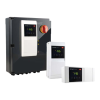
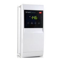
Overview of SmartCella controller capabilities, design, and benefits for cold rooms.
Description of available accessories for SmartCella controllers.
Physical dimensions for single-phase and three-phase SmartCella models.
Instructions for mounting the controller on a wall for different models.
Detailed wiring diagrams for single-phase and three-phase SmartCella versions.
Step-by-step guide for installing the controller, including connections and warnings.
Instructions for using the IROPZKEY00/A0 programming key.
Guide for connecting the remote display to the controller.
Instructions for connecting the controller to a supervisory network via RS485.
Description of the controller's display features and temperature range.
Explanation of the keypad buttons and their functions.
Meaning of the different signal LEDs on the controller.
Guide to modifying operating parameters using the front keypad.
Procedure for setting the desired temperature value (set point).
Instructions for setting frequently-used (F) and configuration (C) parameters.
How to navigate between different parameter categories.
Procedure to restore controller parameters to their default values.
Steps to activate or deactivate the defrost function.
How to switch the controller on and off from the keypad.
Instructions for activating the continuous cycle function.
Setting configuration parameters like date/time, probes, and units.
Procedure to load parameter sets onto the controller.
Final checks before starting the controller after installation and configuration.
Configuration and calibration of analogue inputs for temperature probes.
Assigning functions to digital inputs like alarms, defrost, or door switches.
Configuration of digital outputs for various functions and relay protectors.
Methods to switch the controller ON/OFF via keypad, input, or supervisor.
Definition and usage of the virtual probe for control.
Setting the set point and operating modes (direct, reverse).
Configuration and operation of the pump down function for evaporator emptying.
Enabling autostart for pump down after low pressure signal.
Activating and managing the continuous cycle for lower temperatures.
Functionality and configuration of the anti-sweat heater.
Configuration and control of light and auxiliary outputs.
Setting up defrost events, types, and parameters.
Management of evaporator fans based on temperature and probe readings.
Activation logic for condenser fans based on temperature settings.
Setting compressor running time with duty cycle for fault tolerance.
Function to activate defrost based on evaporator temperature and time.
List of variables accessible through serial communication.
Messages displayed to notify users of control procedures or status.
Classification of alarms: system, control, temperature, and communication.
Procedure for manually resetting alarms from the keypad.
Management and display of HACCP alarms (HA and HF types).
Detailed table listing alarm codes, causes, and associated actions.
Parameters related to alarm activation thresholds and delays.
Parameters for configuring HACCP alarm monitoring and thresholds.
Configuration for high condenser temperature alarm.
Setting and activation of the frost protection alarm.
Alarm generated when defrost exceeds maximum duration.
Detailed electrical and mechanical specifications for single-phase models.
Wiring diagrams for three-phase SmartCella models.
Power circuit diagram for specific three-phase SmartCella models.
Power circuit diagram for other three-phase SmartCella models.
Wiring diagram for the auxiliary circuits of the SmartCella controller.
Connections for pump down operation managed by Smartcella.
Connections for pump down with compressor shutdown due to low pressure.
Connections for pump down with simultaneous compressor and solenoid valve activation.
Connections for simultaneous compressor and solenoid valve activation/deactivation.
Connections for pump down activation/deactivation by time.
Instructions for installing the Visual Parameter Manager software.
Guide to opening and starting the VPM software.
Steps for connecting the computer to the programming key.
Procedure for modifying parameters using the VPM software.
How to add new parameter sets to the controller via VPM.
Procedure for writing parameters from the key to the controller.
Algorithm for adjusting defrost interval based on previous defrost duration.
Configuration for defrost management with two evaporators.
Functionality for second compressor rotation with two-step control.
| Brand | Carel |
|---|---|
| Model | SmartCella 3PH |
| Category | Controller |
| Language | English |