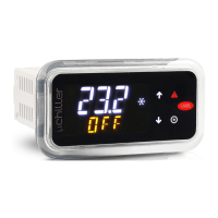
Do you have a question about the Carel uChiller UCHBP00000190 and is the answer not in the manual?
| Brand | Carel |
|---|---|
| Model | uChiller UCHBP00000190 |
| Category | Controller |
| Language | English |
Information on correct handling of waste electrical and electronic equipment (WEEE).
Details on WEEE disposal procedures and regulations for users.
Overview of the primary features and capabilities of the μChiller controller.
Details on the different available models of the μChiller controller.
List and descriptions of optional accessories for the μChiller.
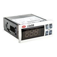
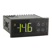
Details on the user terminal for display and keypad functions.
Description of the 4.3" pGDx graphic touch screen terminal.
Information on the EVD Evolution driver for electronic expansion valves.
Information on NTC sensors for temperature measurement in various circuits.
Details on pressure sensors for measuring evaporation and condensing pressure.
Description of the unipolar electronic expansion valve and its usage.
Details on the optional external backup module for the EVD Evolution driver.
Details on the optional external backup module for unipolar valves.
Information on CloudGate for IoT gateways and tERA platform services.
List of connector kits for panel and DIN rail models.
Information on display cables for DIN rail models.
Description of the electronic device for PC interfacing via USB.
Important warnings regarding installation environment and conditions.
Details regarding the panel mounting version of the controller.
Procedure for removing the panel version controller.
Details regarding the DIN rail mounting version of the controller.
Procedure for removing the DIN rail version controller.
General guidelines for electrical installation.
Instructions for connecting probes and digital inputs.
How to connect the user terminal to the controller.
Guidelines for correctly positioning the controller within an electrical panel.
Instructions for serial port connections between two circuits.
Details on connecting the Power+ speed drive for BLDC compressors.
Guidance on optimal placement of probes and components.
Details on configuring analogue inputs for master and slave circuits.
List of parameters for configuring digital inputs.
Parameters for configuring analogue outputs.
Parameters for configuring digital outputs.
Functional diagram for chillers with On/Off compressors and thermostatic expansion valves.
Functional diagram for chillers with free cooling and thermostatic expansion valves.
Functional diagram for chillers/heat pumps with On/Off compressors and bipolar ExV valves.
Functional diagram for chiller/water-to-water heat pumps with On/Off compressors and bipolar ExV valves.
Functional diagram for chillers with On/Off compressors and unipolar ExV valves.
Functional diagram for chillers/heat pumps with BLDC+On/Off compressors and bipolar ExV valves.
Functional diagram for chillers/heat pumps with BLDC+On/Off compressors and bipolar ExV valves.
Using the APPLICA mobile app for configuration via NFC and Bluetooth.
Step-by-step guide for configuring the unit using the APPLICA app.
Steps to configure the unit's parameters using APPLICA.
Steps to configure the controller's inputs and outputs using APPLICA.
Configuring compatibility parameters for legacy mCH2 models.
Setting the unit's date and time using the APPLICA app.
Using APPLICA to clone and replicate unit configurations.
List of unit setup parameters with their default, min, and max values.
Detailed list of I/O configuration parameters for the controller.
Table of mCH2 parameters for legacy models.
Steps to prepare for operation using Applica Desktop.
Setting the refrigerant type using Applica Desktop.
Overview of the μChiller user terminal and its capabilities.
Description of the user terminal's components and interface.
Explanation of the icons indicating device status and operating modes.
Description of the standard display content and behavior.
Accessing direct functions like set point and unit on/off.
Navigating and using the programming mode for parameter adjustment.
Overview of the different programming categories (PLt, EEV, CMP, Src, Clc, Hst).
How the μChiller controls temperature using PID.
Details on proportional control and its parameters for temperature regulation.
Adjusting set points based on outside temperature for improved efficiency.
Managing requests from a BMS system.
Handling and managing high evaporator outlet temperature alarms.
Configuring cyclical pump activation during standby for energy saving.
Managing frost protection alarms based on evaporator conditions.
Setting frost protection thresholds considering refrigerants with glide (e.g., R407C).
Frost protection alarm management using water temperature.
Overview of frost prevention methods and probe configuration.
How frost protection is managed for units with two circuits.
Frost protection measures when the unit is switched off.
Configuring the frost protection heater settings.
Different types of compressor rotation logic (FIFO, Time).
How the controller distributes capacity between circuits and compressors.
Compressor rotation strategy in case of an alarm.
Function to rotate compressors to prevent inactivity issues.
Selecting and configuring predefined BLDC compressors.
Compressor safety time parameters to ensure proper operation.
Managing BLDC compressor start-up according to manufacturer specifications.
Function to ensure oil return to the compressor crankcase.
Managing oil equalisation for tandem BLDC compressors.
Capacity control for compressors in Legacy models.
Overview of BLDC compressor protection mechanisms and operating limits.
Actions taken to prevent BLDC compressors from operating outside limits.
Conditions and delays for compressor shutdown.
How the controller manages the expansion valve functions.
Control modes for modulating and ON-OFF source fans.
Function to reduce fan noise during specific periods.
Fan anti-blocking function for cold climate operation.
Enabling and configuring the free cooling function.
Different types of free cooling configurations.
Free cooling for condensing units with a common air circuit.
Free cooling for air-cooled condensing units with separate air circuits.
Free cooling for water-cooled condensing units.
Dynamic control gain for balancing free cooling and evaporator capacity.
Control to ensure unit operation when free cooling alone is insufficient.
Managing valve anti-block to prevent mechanical issues.
Step-by-step procedure for the defrost function.
Using fans for defrost in specific conditions to improve efficiency.
Adjusting defrost delay based on outside air temperature for better performance.
Synchronizing defrost procedures for units with two circuits.
Managing the user fan on air/air units.
Hot-start and hot-keep functions for heating mode on air/air units.
Deactivating compressors based on outside temperature for energy efficiency.
Requesting operations via the BMS.
Requesting operations via digital inputs.
Automatic changeover based on outside air temperature.
Automatic changeover based on air return temperature for A/A units.
Automatic changeover based on delivery water temperature for A/W and W/W units.
Table of system-related parameters.
Table of compressor-related parameters.
Table of parameters for BLDC compressors and inverters.
Table of parameters related to valves, including ExV.
Table of parameters related to source fans and pumps.
Table of input/output configuration parameters.
Table of mCH2 parameters for legacy models.
Table of parameters for BMS port configuration.
Table of password parameters for different access levels.
Table of parameters displayed on the dashboard.
Table of general settings parameters.
Supervisor table for coil status variables.
Supervisor table for input status variables.
Supervisor table for holding register variables.
Supervisor table for input register variables.
Classification of alarms based on reset modes.
Comprehensive list of alarms, their causes, and reset procedures.
Physical dimensions, materials, and environmental conditions.
Electrical ratings, power supply, and protection class details.
Specifications for the user interface components like buzzer and display.
Details on NFC, Bluetooth, and serial interface connectivity.
Specifications for analogue inputs, including NTC, 0-5V, and 4-20mA types.
Specifications for digital outputs, including voltage and current ratings.
Information on the emergency power supply, specifically the Ultracap module.
Specifications for probe and terminal power supplies.
Details on BMS and FieldBus serial port specifications.
Compliance with electrical safety and electromagnetic compatibility standards.


