µchiller +0500144EZ - rel. 1.2 - 10.07.2018
ENG
CHI
CHI
说明
Chiller是CAREL为全面控制风/水和水/水冷水机组以及热泵机组而开发
的新解决方案。最高配置可管理每个回路2台压缩机(开/关式或BLDC
变频压缩机),最多可控制2个回路(在回路2上采用输入和输出点扩展卡)
。Chiller最突出的元素在于通过电子膨胀阀和无刷DC压缩机的集成管
理实现高效的全面控制,从而确保更好地保护压缩机以及更出色的稳
定性,机组的高效率。使用手操器可以利用移动设备进行无线通讯,
可集成到板载型,如果采用DIN导轨安装型,则需单独订购。
CAREL “APPLICA” 应用,可在Google Play中下载,适用于Android操作系
统,进行设施的参数配置以及现场机组调试。详细操作说明请参考
Chiller用户手册+ 0300053EN,采购前即可从www.carel.com网站下载 。
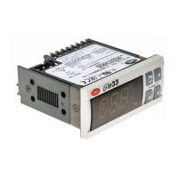
手操器
3
1
Fig. 1
图标
1
按键
2
主显示区
3 图标:设备状态 & 运
行模式
图标
图标 功能 开启 闪烁
系统泵 动作 手动操作
源设备状态状态(
泵/风机)
动作 手动操作
压缩机状态 动作
手动操作
(带ExV)
防雾加热 动作
-
运行模式
制热
-
制冷 高水温报警
除霜 除霜后滴水
自然冷却
-
服务 超出运行时间外的服
务请求
严重报警,需要资
质人员处理
按键
按键 功能
UP 浏览:前一个参数
参数设定:增加显示的值
DOWN 浏览:下一个参数
参数设定:减少显示的值
主菜单:
短时按下:显示机组概况
按下并持续3秒:进入用户信息参数(设定值,机组开-关
...)
Alarm
短时按下:显示动作的报警和使蜂鸣器静音
按下并持续3秒:报警复位
PRG
浏览时:进入参数设定菜单
参数设置时:
• 短时按下:确认值
• 按下并持续3秒:返回到主菜单
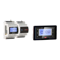
移动设备
“Applica” 应用可以用于通过移动设备(智能手机,平板电脑)配置µChiller
控制器,采用NFC (近场通信)或BLE (或低功耗蓝牙)技术。步骤(修改参
数)如下:
1. 从Google应用商店下载Android适用的CAREL “Applica”应用;
2. (在移动设备上)启用NFC/蓝牙通信以及数据连接;
3. 打开引用;
使用NFC
• 将移动设备靠近手操器,最长距离10 mm,以识别配置(Fig. 2 - ref. A);
• 输入密码 (*);
• 设定所需的参数;
• 将移动设备再次靠近手操器以上载配置参数(Fig. 2 - ref. B);
使用BLE
• 将移动设备靠近手操器,最长距离10 m,以识别配置(Fig. 2 - ref. C);
• 输入密码 (*);
• 设定所需的参数;
(*)由冷水机组制造商预分配,为授权服务技术员进行维护专用。
重要:第一次连接时,应用程序通过云连接使其自身与µChiller控制
器上的软件版本匹配;这表明至少第一次连接需要移动数据连接。
Fig. 2
调试
初次调试的步骤请参考下述说明。
准备
在第一次配置机组前,请先访问KSA (ksa.carel.com),选择“Congurations”
(配置)文件夹,并且:
1. 对于Chiller标准版和加强版(使用开/关压缩机),选择“Refrigerants” (
制冷剂)模块,然后是机组充注的制冷剂;
2. 对于HE型(使用BLDC压缩机),导入BLDC配置,选择“BLDC compressors”
(BLDC压缩机)模板,然后是安装在机组上的压缩机品牌和型号(已经包
含了制冷剂设定)
3. 将下载的配置导入到移动设备中。
配置
1. 启动应用并进入Manufacturer(制造商)和Service(服务)界面;
2. 选择Set-up -> Conguration(设定->配置)并点击 + 图标图标(如图)
3. 使用菜单(Fig. a)选择并应用所需的配置;
4. 选择Unit Set-up(机组设定) (Fig. b)进行完整的配置(Fig c)。
a
b
c
报警表
代码 说明
A001
机组:无永久内存写入
A002
机组:永久内存写入
A003
机组:数字量输入点远程报警
A004
机组:传感器远程设定点
A005
机组:用户回水温度传感器
A006
机组:用户供水温度传感器
A008
机组:用户泵1过载
A009
机组:用户泵2过载
A10
机组:流量开关(用户泵1是动作的)
A11
机组:流量开关(用户泵2是动作的)
A12
机组:用户泵组
A13
机组:用户泵1维护
A14
机组:用户泵2维护
A15
机组:高冷却的水温
A16
机组:源回水/回风温度传感器
A17
机组:源泵1维护
A18
机组:自然冷却警告
A19
回路1:排气压力传感器
A20
回路1:冷凝温度传感器
A21
回路1:吸气压力传感器
A22
回路1:蒸发温度传感器
A23
回路1:排气温度传感器
A24
回路1:吸气温度传感器
A25
回路1:高压开关
A26
回路1:高压变送器
A27
回路1:低压变送器
A28
回路1:防雾保护蒸发温度
A30
回路1:压缩机1过载
A31
回路1:压缩机2过载
A32
回路1:压缩机1维护
A33
回路1:压缩机2维护
A34
回路1:源风机维护
A35
EVD回路1:LowSH
A36
EVD回路1:LOP
A37
EVD回路1:MOP
A38
EVD回路1:电机故障
A39
EVD回路1:紧急关闭
A40
EVD回路1:阀未完全关闭
A41
EVD回路1:掉线
A42
回路1:区间报警 + 区域报警
A43
BLDC回路1:启动时高压差分
A44
BLDC回路1:启动时失败
A45
BLDC回路1:低压差分
A46
BLDC回路1:高排气温度
A47
速度驱动器1:掉线
A48
速度驱动器1:报警 + 故障代码
A49
机组:从机掉线
A50
从机:无永久内存写入
A51
从机:永久内存写入
A52
回路2:排气压力传感器
A53
回路2:冷凝温度传感器
A54
回路2:吸气压力传感器
A55
回路2:蒸发温度传感器
A56
回路2:排气温度传感器
A57
回路2:吸气温度传感器
A58
回路2:高压开关
A59
回路2:高压变送器
A60
回路2:低压变送器
A61
回路2:防雾保护蒸发温度
A63
回路2:压缩机1过载
A64
回路2:压缩机2过载
A65
回路2:压缩机1维护
A66
回路2:压缩机2维护
A67
回路2:源风机维护
A68
EVD回路2:LowSH
A69
EVD回路2:LOP
A70
EVD回路2:MOP
A71
EVD回路2:电机故障
A72
EVD回路2:紧急关闭
A73
EVD回路2:阀未完全关闭
A74
EVD回路2:掉线
A75
回路2:区间报警 + 区域报警
A76
BLDC回路2:启动时高压差分
A77
BLDC回路2:启动时失败
A78
BLDC回路2:低压差分
A79
BLDC回路2:高排气温度
A80
速度驱动器2:掉线
A81
速度驱动器2:报警 + 故障代码
技术规格 (适用于两个型号)
技术规格, μChiller面板安装型和DIN导轨安装型
物理规格
尺寸 参考附图
外壳 聚碳酸酯
装配
UCHBP*: 面板安装型
UCHBD*: DIN导轨安装型
球压测试温度
125°C
防护等级
IP20 (背板,面板安装型)
IP65 (前盖板,面板安装型)
IP00 (DIN导轨安装型)
表面清洁 使用温和的,非磨损织物和中性清洁剂或水
环境条件
运行条件
-20~60°C, <90% RH 无凝露
储存条件
-40~85°C, <90% RH 无凝露
电气规格
额定电压
SELV或PELV 2类电源
工作电压
24 Vac/dc, +10% -15%;
输入频率
50/60Hz
最大电流消耗
600 mArms
最小功耗
400mW
时钟
精度 ± 50ppm; 停机后日期/时间保持:72小时
软件等级和结构
A
环境污染等级
抗电击保护等级
集成中 I或 II设备
动作和断开类型
1.C
额定脉冲电压
继电器输出:4kV; 24 V 输入0.5 kV
浪涌抗扰度类别
浪涌抗扰度III类; 24 V输入:II类
控制设备结构 集成设备
连接端子 即插式
接线尺寸:参考连接端子表
控制目的 电子操作控制
用户手操器
蜂鸣器
面板安装型:集成
DIN导轨安装型:控制器不内置,集成在用户手操器上
显示屏
LED 2行,小数点,多功能图标
通讯
NFC 最大距离10mm,根据所用的移动设备
会变动
低功耗蓝牙
最大距离10m,根据所用的移动设备会
变动
BMS串接口 Modbus RS485通讯,非光隔离
FieldBUS串接口 Modbus RS485通讯,非光隔离
HMI接口 Modbus RS485通讯,非光隔离
模拟量输入 (最长距离=10m)
Ref.
J2
S1, S2, S3: NTC NTC:精度0.1° C;10k @ 25°C;
容差:±1°C,量程 -50T50°C;
±3°C,量程50T90°C
0-10 V:容差为满量程的2%;一般为1%
4-20mA:容差为满量程的5%;一般
为1%
0-10 V:容差为满量程的2%;一般为1%
S5: 0-5V rat /4-20 mA / NTC
J3
S4: 0-5V rat /4-20 mA / NTC
S6: NTC / 0-5 Vrat / 0-10 V
/ 4-20 mA
J9
S7: NTC - 仅
DIN导轨安装
型适用
数字量输入
Ref.
J2 ID1
(*)
无源触点,非光隔离,常闭电流6 mA,
触点打开电压:13 V,
触点电阻最大为50
(*) 快速数字量输入:
0-2 kHz;容差为满
量程的2%
J2 ID2
J3 ID3 (*), ID4, ID5,
J9
ID6
- 仅
DIN导轨安
装型适用
阀输出
Ref.
J14 仅
DIN导轨安装型适用
CAREL E*V 单对极阀电源:最小13 Vdc,
线圈电阻40
模拟量输出
Ref.
J2 Y1, Y2 0-10V: 10 mA最大
数字量输出
Ref.
J6
NO1 (5A), NO2 (5A),
NO3 (5A), NO4 (5A)
5A: EN60730: 5 A 阻抗, 250 Vac, 5万次动作; 4(1),
230 Vac, 100k cycles; 3 (1), 230 Vac, 10万次动作
UL60730: 5 A 阻抗, 250 Vac, 3万次动作; 1 FLA,
6 LRA, 250 Vac, 3万次动作; Pilot Duty C300, 3
万次动作
J7 NO5 (5A)
J11
NO6 (5A)- 仅
DIN导轨
安装型适用
备注:NO1, NO2, NO3和NO4触点的电流消耗不能超过 8A。
紧急供电
Ref.
J10 超级电容模块(可选的,仅
DIN导轨安装型适用
) 13 Vdc +/-10%
传感器和接线端电源
5V
5 Vdc ± 2%向0 ~ 5 V公制比率式传感器供电。最大传输电流:10
mA,短路保护
+V
8-11 V向4-20 mA电流传感器供电。最大传输电流:25 mA ,短路
保护
J8 13 Vdc ± 10%向手操器供电
VL
未使用
线缆长度
模拟量输入/输出,数字量
输入/输出,传感器电源
<10m (*) (**)
(*)对于面板安装型,如果在住宅环境中使
用VL电源,线缆最长为2 m
(**)对于115 Vac DIN导轨安装型,如果在
住宅环境中使用+V电源,线缆最长为2 m
阀
< 2 m, < 6 m 使用屏蔽线
BMS和Fieldbus串行线 <500m,使用屏蔽线
合规性
电气安全
EN/UL 60730-1, EN/UL 60335-1
电磁兼容性
EN 61000-6-1, EN 61000-6-2, EN 61000-6-3,
EN 61000-6-4
与可然制冷剂气体应用
EN/UL 60079-15, EN/UL 60335-2-34,
EN/UL 60335-2-40, EN/UL 60335-2-89
无线
RED, FCC, IC
ENG
Description
Chiller is the Carel solution for complete management of air/water and wa-
ter/water chillers and heat pumps. The maximum conguration manages 2
compressors per circuit (On/O or BLDC), up to a maximum of 2 circuits (using
an expansion card for the inputs and outputs on circuit 2). The distinctive ele-
ment of Chiller is complete control of high-eciency units through integrat-
ed management of electronic expansion valves and brushless DC compressor,
thus ensuring greater compressor protection and reliability, together with
high unit eciency. The user terminal allows wireless connectivity with mo-
bile devices and is integrated into the panel-mounted models, or purchased
separately on DIN rail mounted models. The CAREL “APPLICA” app, available on
Google Play for the Android operating system, facilitates conguration of the
parameters and unit commissioning in the eld. The operation of Chiller is
described in the user manual + 0300053EN downloadable, even prior to pur-
chase, from the website www.carel.com.
USER TERMINAL
3
1
Fig. 1
key
1 Keypad
2 Main eld
3 Icons: device status &
operating mode
Icons
Icon Function On Flashing
System pump Active Manual operation
Source device status
(pump/fan)
Active Manual operation
Compressor status Active Manual operation
(with ExV)
Frost protection
heater
Active -
Operating
mode
Heating -
Cooling High water tempera-
ture alarm
Defrost Dripping after defrost
Free cooling -
Service Service request on
exceeding operating
hours
Serious alarm, action
required by qualied
personnel
Keypad
Button Function
UP Navigation: previous parameter
Parameter setting: increase value
DOWN Navigation: next parameter
Parameter setting: decrease value displayed.
MAIN MENU:
Pressed briey: unit overview display
Pressed and held (3 s): access user prole parameters (set
point, unit on-o, ...)
Alarm Pressed briey: display active alarms and mute buzzer.
Pressed and held (3 s): reset alarms.
PRG
During navigation: access the parameter setting menu
During parameter setting:
• pressed briey: conrm the value
• pressed and held (3 s): return to the main menu
MOBILE DEVICE
The “Applica” app can be used to congure the µChiller controller from a mo-
bile device (smartphone, tablet), via NFC (Near Field Communication) or BLE
(Bluetooth Low Energy). Procedure (modify parameters):
1. download the CAREL “Applica” app for Android devices from Google Play Store;
2. (on the mobile device) activate NFC/Bluetooth communication and data
connection;
3. open Applica;
Using NFC
• move the mobile device near to the user terminal, maximum distance 10
mm, so as to recognise the conguration (Fig. 2 - ref. A);
• enter the password (*);
• set the parameters as needed;
• move the mobile device near to the user terminal again to upload the con-
guration parameters (Fig. 2 - ref. B);
Using BLE
• move the mobile device near to the user terminal, maximum distance 10 m,
to recognise the conguration (Fig. 2 - ref. C);
• enter the password (*);
• set the parameters as needed.
(*) pre-assigned by the chiller manufacturer to allow maintenance only by au-
thorised service technicians.
µChiller 冷水/热泵机组电子控制器/ Electronic control for chiller and heat pump
µchiller +0500144EZ - rel. 1.2 - 10.07.2018
ENG
CHI
CHI
说明
Chiller是CAREL为全面控制风/水和水/水冷水机组以及热泵机组而开发
的新解决方案。最高配置可管理每个回路2台压缩机(开/关式或BLDC
变频压缩机),最多可控制2个回路(在回路2上采用输入和输出点扩展卡)
。Chiller最突出的元素在于通过电子膨胀阀和无刷DC压缩机的集成管
理实现高效的全面控制,从而确保更好地保护压缩机以及更出色的稳
定性,机组的高效率。使用手操器可以利用移动设备进行无线通讯,
可集成到板载型,如果采用DIN导轨安装型,则需单独订购。
CAREL “APPLICA” 应用,可在Google Play中下载,适用于Android操作系
统,进行设施的参数配置以及现场机组调试。详细操作说明请参考
Chiller用户手册+ 0300053EN,采购前即可从www.carel.com网站下载 。
手操器
3
1
Fig. 1
图标
1
按键
2
主显示区
3 图标:设备状态 & 运
行模式
图标
图标 功能 开启 闪烁
系统泵 动作 手动操作
源设备状态状态(
泵/风机)
动作 手动操作
压缩机状态 动作
手动操作
(带ExV)
防雾加热 动作
-
运行模式
制热
-
制冷 高水温报警
除霜 除霜后滴水
自然冷却
-
服务 超出运行时间外的服
务请求
严重报警,需要资
质人员处理
按键
按键 功能
UP 浏览:前一个参数
参数设定:增加显示的值
DOWN 浏览:下一个参数
参数设定:减少显示的值
主菜单:
短时按下:显示机组概况
按下并持续3秒:进入用户信息参数(设定值,机组开-关
...)
Alarm
短时按下:显示动作的报警和使蜂鸣器静音
按下并持续3秒:报警复位
PRG
浏览时:进入参数设定菜单
参数设置时:
• 短时按下:确认值
• 按下并持续3秒:返回到主菜单
移动设备
“Applica” 应用可以用于通过移动设备(智能手机,平板电脑)配置µChiller
控制器,采用NFC (近场通信)或BLE (或低功耗蓝牙)技术。步骤(修改参
数)如下:
1. 从Google应用商店下载Android适用的CAREL “Applica”应用;
2. (在移动设备上)启用NFC/蓝牙通信以及数据连接;
3. 打开引用;
使用NFC
• 将移动设备靠近手操器,最长距离10 mm,以识别配置(Fig. 2 - ref. A);
• 输入密码 (*);
• 设定所需的参数;
• 将移动设备再次靠近手操器以上载配置参数(Fig. 2 - ref. B);
使用BLE
• 将移动设备靠近手操器,最长距离10 m,以识别配置(Fig. 2 - ref. C);
• 输入密码 (*);
• 设定所需的参数;
(*)由冷水机组制造商预分配,为授权服务技术员进行维护专用。
重要:第一次连接时,应用程序通过云连接使其自身与µChiller控制
器上的软件版本匹配;这表明至少第一次连接需要移动数据连接。
Fig. 2
调试
初次调试的步骤请参考下述说明。
准备
在第一次配置机组前,请先访问KSA (ksa.carel.com),选择“Congurations”
(配置)文件夹,并且:
1. 对于Chiller标准版和加强版(使用开/关压缩机),选择“Refrigerants” (
制冷剂)模块,然后是机组充注的制冷剂;
2. 对于HE型(使用BLDC压缩机),导入BLDC配置,选择“BLDC compressors”
(BLDC压缩机)模板,然后是安装在机组上的压缩机品牌和型号(已经包
含了制冷剂设定)
3. 将下载的配置导入到移动设备中。
配置
1. 启动应用并进入Manufacturer(制造商)和Service(服务)界面;
2. 选择Set-up -> Conguration(设定->配置)并点击 + 图标图标(如图)
3. 使用菜单(Fig. a)选择并应用所需的配置;
4. 选择Unit Set-up(机组设定) (Fig. b)进行完整的配置(Fig c)。
a
b
c
报警表
代码 说明
A001
机组:无永久内存写入
A002
机组:永久内存写入
A003
机组:数字量输入点远程报警
A004
机组:传感器远程设定点
A005
机组:用户回水温度传感器
A006
机组:用户供水温度传感器
A008
机组:用户泵1过载
A009
机组:用户泵2过载
A10
机组:流量开关(用户泵1是动作的)
A11
机组:流量开关(用户泵2是动作的)
A12
机组:用户泵组
A13
机组:用户泵1维护
A14
机组:用户泵2维护
A15
机组:高冷却的水温
A16
机组:源回水/回风温度传感器
A17
机组:源泵1维护
A18
机组:自然冷却警告
A19
回路1:排气压力传感器
A20
回路1:冷凝温度传感器
A21
回路1:吸气压力传感器
A22
回路1:蒸发温度传感器
A23
回路1:排气温度传感器
A24
回路1:吸气温度传感器
A25
回路1:高压开关
A26
回路1:高压变送器
A27
回路1:低压变送器
A28
回路1:防雾保护蒸发温度
A30
回路1:压缩机1过载
A31
回路1:压缩机2过载
A32
回路1:压缩机1维护
A33
回路1:压缩机2维护
A34
回路1:源风机维护
A35
EVD回路1:LowSH
A36
EVD回路1:LOP
A37
EVD回路1:MOP
A38
EVD回路1:电机故障
A39
EVD回路1:紧急关闭
A40
EVD回路1:阀未完全关闭
A41
EVD回路1:掉线
A42
回路1:区间报警 + 区域报警
A43
BLDC回路1:启动时高压差分
A44
BLDC回路1:启动时失败
A45
BLDC回路1:低压差分
A46
BLDC回路1:高排气温度
A47
速度驱动器1:掉线
A48
速度驱动器1:报警 + 故障代码
A49
机组:从机掉线
A50
从机:无永久内存写入
A51
从机:永久内存写入
A52
回路2:排气压力传感器
A53
回路2:冷凝温度传感器
A54
回路2:吸气压力传感器
A55
回路2:蒸发温度传感器
A56
回路2:排气温度传感器
A57
回路2:吸气温度传感器
A58
回路2:高压开关
A59
回路2:高压变送器
A60
回路2:低压变送器
A61
回路2:防雾保护蒸发温度
A63
回路2:压缩机1过载
A64
回路2:压缩机2过载
A65
回路2:压缩机1维护
A66
回路2:压缩机2维护
A67
回路2:源风机维护
A68
EVD回路2:LowSH
A69
EVD回路2:LOP
A70
EVD回路2:MOP
A71
EVD回路2:电机故障
A72
EVD回路2:紧急关闭
A73
EVD回路2:阀未完全关闭
A74
EVD回路2:掉线
A75
回路2:区间报警 + 区域报警
A76
BLDC回路2:启动时高压差分
A77
BLDC回路2:启动时失败
A78
BLDC回路2:低压差分
A79
BLDC回路2:高排气温度
A80
速度驱动器2:掉线
A81
速度驱动器2:报警 + 故障代码
技术规格 (适用于两个型号)
技术规格, μChiller面板安装型和DIN导轨安装型
物理规格
尺寸 参考附图
外壳 聚碳酸酯
装配
UCHBP*: 面板安装型
UCHBD*: DIN导轨安装型
球压测试温度
125°C
防护等级
IP20 (背板,面板安装型)
IP65 (前盖板,面板安装型)
IP00 (DIN导轨安装型)
表面清洁 使用温和的,非磨损织物和中性清洁剂或水
环境条件
运行条件
-20~60°C, <90% RH 无凝露
储存条件
-40~85°C, <90% RH 无凝露
电气规格
额定电压
SELV或PELV 2类电源
工作电压
24 Vac/dc, +10% -15%;
输入频率
50/60Hz
最大电流消耗
600 mArms
最小功耗
400mW
时钟
精度 ± 50ppm; 停机后日期/时间保持:72小时
软件等级和结构
A
环境污染等级
抗电击保护等级
集成中 I或 II设备
动作和断开类型
1.C
额定脉冲电压
继电器输出:4kV; 24 V 输入0.5 kV
浪涌抗扰度类别
浪涌抗扰度III类; 24 V输入:II类
控制设备结构 集成设备
连接端子 即插式
接线尺寸:参考连接端子表
控制目的 电子操作控制
用户手操器
蜂鸣器
面板安装型:集成
DIN导轨安装型:控制器不内置,集成在用户手操器上
显示屏
LED 2行,小数点,多功能图标
通讯
NFC 最大距离10mm,根据所用的移动设备
会变动
低功耗蓝牙
最大距离10m,根据所用的移动设备会
变动
BMS串接口 Modbus RS485通讯,非光隔离
FieldBUS串接口 Modbus RS485通讯,非光隔离
HMI接口 Modbus RS485通讯,非光隔离
模拟量输入 (最长距离=10m)
Ref.
J2
S1, S2, S3: NTC NTC:精度0.1° C;10k @ 25°C;
容差:±1°C,量程 -50T50°C;
±3°C,量程50T90°C
0-10 V:容差为满量程的2%;一般为1%
4-20mA:容差为满量程的5%;一般
为1%
0-10 V:容差为满量程的2%;一般为1%
S5: 0-5V rat /4-20 mA / NTC
J3
S4: 0-5V rat /4-20 mA / NTC
S6: NTC / 0-5 Vrat / 0-10 V
/ 4-20 mA
J9
S7: NTC - 仅
DIN导轨安装
型适用
数字量输入
Ref.
J2 ID1
(*)
无源触点,非光隔离,常闭电流6 mA,
触点打开电压:13 V,
触点电阻最大为50
(*) 快速数字量输入:
0-2 kHz;容差为满
量程的2%
J2 ID2
J3 ID3 (*), ID4, ID5,
J9
ID6
- 仅
DIN导轨安
装型适用
阀输出
Ref.
J14 仅
DIN导轨安装型适用
CAREL E*V 单对极阀电源:最小13 Vdc,
线圈电阻40
模拟量输出
Ref.
J2 Y1, Y2 0-10V: 10 mA最大
数字量输出
Ref.
J6
NO1 (5A), NO2 (5A),
NO3 (5A), NO4 (5A)
5A: EN60730: 5 A 阻抗, 250 Vac, 5万次动作; 4(1),
230 Vac, 100k cycles; 3 (1), 230 Vac, 10万次动作
UL60730: 5 A 阻抗, 250 Vac, 3万次动作; 1 FLA,
6 LRA, 250 Vac, 3万次动作; Pilot Duty C300, 3
万次动作
J7 NO5 (5A)
J11
NO6 (5A)- 仅
DIN导轨
安装型适用
备注:NO1, NO2, NO3和NO4触点的电流消耗不能超过 8A。
紧急供电
Ref.
J10 超级电容模块(可选的,仅
DIN导轨安装型适用
) 13 Vdc +/-10%
传感器和接线端电源
5V
5 Vdc ± 2%向0 ~ 5 V公制比率式传感器供电。最大传输电流:10
mA,短路保护
+V
8-11 V向4-20 mA电流传感器供电。最大传输电流:25 mA ,短路
保护
J8 13 Vdc ± 10%向手操器供电
VL
未使用
线缆长度
模拟量输入/输出,数字量
输入/输出,传感器电源
<10m (*) (**)
(*)对于面板安装型,如果在住宅环境中使
用VL电源,线缆最长为2 m
(**)对于115 Vac DIN导轨安装型,如果在
住宅环境中使用+V电源,线缆最长为2 m
阀
< 2 m, < 6 m 使用屏蔽线
BMS和Fieldbus串行线 <500m,使用屏蔽线
合规性
电气安全
EN/UL 60730-1, EN/UL 60335-1
电磁兼容性
EN 61000-6-1, EN 61000-6-2, EN 61000-6-3,
EN 61000-6-4
与可然制冷剂气体应用
EN/UL 60079-15, EN/UL 60335-2-34,
EN/UL 60335-2-40, EN/UL 60335-2-89
无线
RED, FCC, IC
ENG
Description
Chiller is the Carel solution for complete management of air/water and wa-
ter/water chillers and heat pumps. The maximum conguration manages 2
compressors per circuit (On/O or BLDC), up to a maximum of 2 circuits (using
an expansion card for the inputs and outputs on circuit 2). The distinctive ele-
ment of Chiller is complete control of high-eciency units through integrat-
ed management of electronic expansion valves and brushless DC compressor,
thus ensuring greater compressor protection and reliability, together with
high unit eciency. The user terminal allows wireless connectivity with mo-
bile devices and is integrated into the panel-mounted models, or purchased
separately on DIN rail mounted models. The CAREL “APPLICA” app, available on
Google Play for the Android operating system, facilitates conguration of the
parameters and unit commissioning in the eld. The operation of Chiller is
described in the user manual + 0300053EN downloadable, even prior to pur-
chase, from the website www.carel.com.
USER TERMINAL
3
1
Fig. 1
key
1 Keypad
2 Main eld
3 Icons: device status &
operating mode
Icons
Icon Function On Flashing
System pump Active Manual operation
Source device status
(pump/fan)
Active Manual operation
Compressor status Active Manual operation
(with ExV)
Frost protection
heater
Active -
Operating
mode
Heating -
Cooling High water tempera-
ture alarm
Defrost Dripping after defrost
Free cooling -
Service Service request on
exceeding operating
hours
Serious alarm, action
required by qualied
personnel
Keypad
Button Function
UP Navigation: previous parameter
Parameter setting: increase value
DOWN Navigation: next parameter
Parameter setting: decrease value displayed.
MAIN MENU:
Pressed briey: unit overview display
Pressed and held (3 s): access user prole parameters (set
point, unit on-o, ...)
Alarm Pressed briey: display active alarms and mute buzzer.
Pressed and held (3 s): reset alarms.
PRG
During navigation: access the parameter setting menu
During parameter setting:
• pressed briey: conrm the value
• pressed and held (3 s): return to the main menu
MOBILE DEVICE
The “Applica” app can be used to congure the µChiller controller from a mo-
bile device (smartphone, tablet), via NFC (Near Field Communication) or BLE
(Bluetooth Low Energy). Procedure (modify parameters):
1. download the CAREL “Applica” app for Android devices from Google Play Store;
2. (on the mobile device) activate NFC/Bluetooth communication and data
connection;
3. open Applica;
Using NFC
• move the mobile device near to the user terminal, maximum distance 10
mm, so as to recognise the conguration (Fig. 2 - ref. A);
• enter the password (*);
• set the parameters as needed;
• move the mobile device near to the user terminal again to upload the con-
guration parameters (Fig. 2 - ref. B);
Using BLE
• move the mobile device near to the user terminal, maximum distance 10 m,
to recognise the conguration (Fig. 2 - ref. C);
• enter the password (*);
• set the parameters as needed.
(*) pre-assigned by the chiller manufacturer to allow maintenance only by au-
thorised service technicians.
µChiller 冷水/热泵机组电子控制器/ Electronic control for chiller and heat pump