µRack
Cod. CAREL +03P220431 rel. 2.2 dated 10/02/12
30
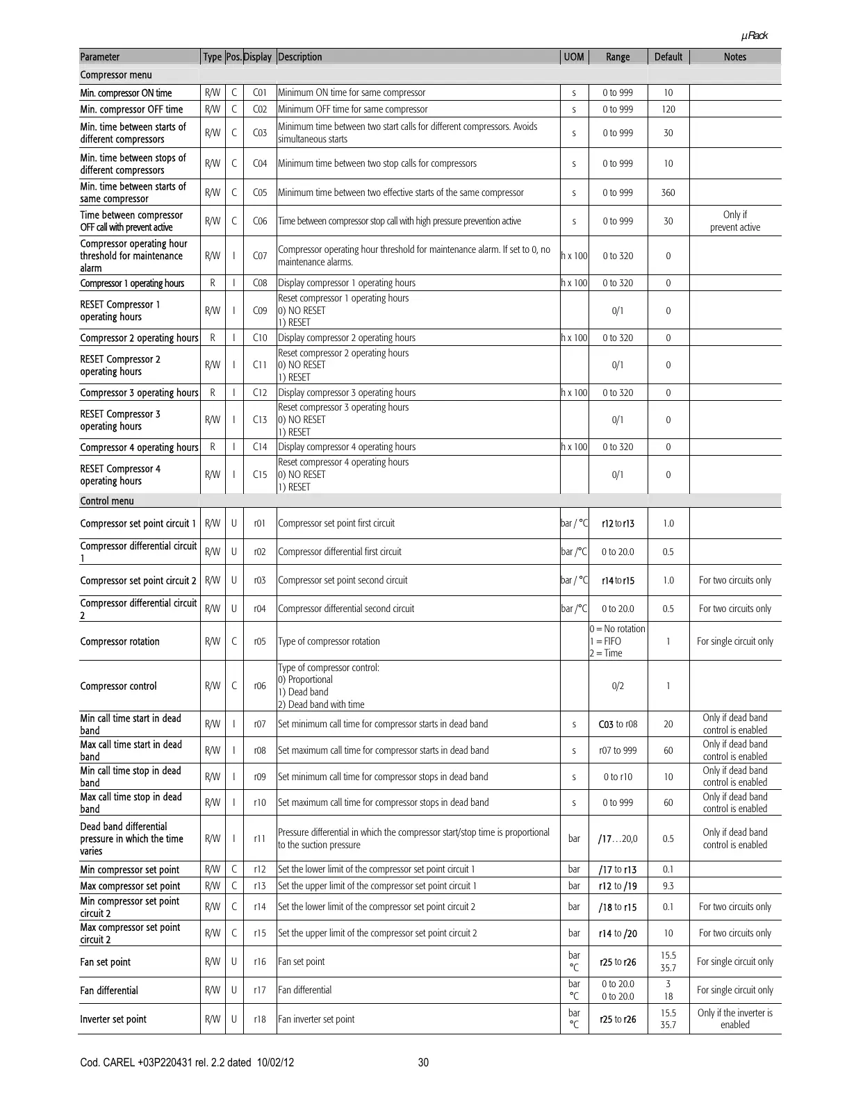
Parameter Type Pos. Display Description UOM Range Default Notes
Compressor menu
Min. compressor ON time R/W C C01 Minimum ON time for same compressor s 0 to 999 10
Min. compressor OFF time R/W C C02 Minimum OFF time for same compressor s 0 to 999 120
Min. time between starts of
different compressors
R/W C C03
Minimum time between two start calls for different compressors. Avoids
simultaneous starts
s 0 to 999 30
Min. time between stops of
different compressors
R/W C C04 Minimum time between two stop calls for compressors s 0 to 999 10
Min. time between starts of
same compressor
R/W C C05 Minimum time between two effective starts of the same compressor s 0 to 999 360
Time between compressor
OFF call with prevent active
R/W C C06 Time between compressor stop call with high pressure prevention active s 0 to 999 30
Only if
prevent active
Compressor operating hour
threshold for maintenance
alarm
R/W I C07
Compressor operating hour threshold for maintenance alarm. If set to 0, no
maintenance alarms.
h x 100 0 to 320 0
Compressor 1 operating hours R I C08 Display compressor 1 operating hours h x 100 0 to 320 0
RESET Compressor 1
operating hours
R/W I C09
Reset compressor 1 operating hours
0) NO RESET
1) RESET
0/1 0
Compressor 2 operating hours R I C10 Display compressor 2 operating hours h x 100 0 to 320 0
RESET Compressor 2
operating hours
R/W I C11
Reset compressor 2 operating hours
0) NO RESET
1) RESET
0/1 0
Compressor 3 operating hours R I C12 Display compressor 3 operating hours h x 100 0 to 320 0
RESET Compressor 3
operating hours
R/W I C13
Reset compressor 3 operating hours
0) NO RESET
1) RESET
0/1 0
Compressor 4 operating hours R I C14 Display compressor 4 operating hours h x 100 0 to 320 0
RESET Compressor 4
operating hours
R/W I C15
Reset compressor 4 operating hours
0) NO RESET
1) RESET
0/1 0
Control menu
Compressor set point circuit 1 R/W U r01 Compressor set point first circuit bar / °C r12 to r13 1.0
Compressor differential circuit
1
R/W U r02 Compressor differential first circuit bar /°C 0 to 20.0 0.5
Compressor set point circuit 2 R/W U r03 Compressor set point second circuit bar / °C r14 to r15 1.0 For two circuits only
Compressor differential circuit
2
R/W U r04 Compressor differential second circuit bar /°C 0 to 20.0 0.5 For two circuits only
Compressor rotation R/W C r05 Type of compressor rotation
0 = No rotation
1 = FIFO
2 = Time
1 For single circuit only
Compressor control R/W C r06
Type of compressor control:
0) Proportional
1) Dead band
2) Dead band with time
0/2 1
Min call time start in dead
band
R/W I r07 Set minimum call time for compressor starts in dead band s C03 to r08 20
Only if dead band
control is enabled
Max call time start in dead
band
R/W I r08 Set maximum call time for compressor starts in dead band s r07 to 999 60
Only if dead band
control is enabled
Min call time stop in dead
band
R/W I r09 Set minimum call time for compressor stops in dead band s 0 to r10 10
Only if dead band
control is enabled
Max call time stop in dead
band
R/W I r10 Set maximum call time for compressor stops in dead band s 0 to 999 60
Only if dead band
control is enabled
Dead band differential
pressure in which the time
varies
R/W I r11
Pressure differential in which the compressor start/stop time is proportional
to the suction pressure
bar /17…20,0 0.5
Only if dead band
control is enabled
Min compressor set point R/W C r12 Set the lower limit of the compressor set point circuit 1 bar /17 to r13 0.1
Max compressor set point R/W C r13 Set the upper limit of the compressor set point circuit 1 bar r12 to /19 9.3
Min compressor set point
circuit 2
R/W C r14 Set the lower limit of the compressor set point circuit 2 bar /18 to r15 0.1 For two circuits only
Max compressor set point
circuit 2
R/W C r15 Set the upper limit of the compressor set point circuit 2 bar r14 to /20 10 For two circuits only
Fan set point R/W U r16 Fan set point
bar
°C
r25 to r26
15.5
35.7
For single circuit only
Fan differential R/W U r17 Fan differential
bar
°C
0 to 20.0
0 to 20.0
3
18
For single circuit only
Inverter set point R/W U r18 Fan inverter set point
bar
°C
r25 to r26
15.5
35.7
Only if the inverter is
enabled