µRack
Cod. CAREL +03P220431 rel. 2.2 dated 10/02/12
21
5.4 PWM-PPM management
On the controller, the “fan control” output generates a PWM signal.
This output is used to drive phase control modules that directly control the fan speed.
The output, depending on how it is configured, can generate a pulse width modulation (PWM) signal.
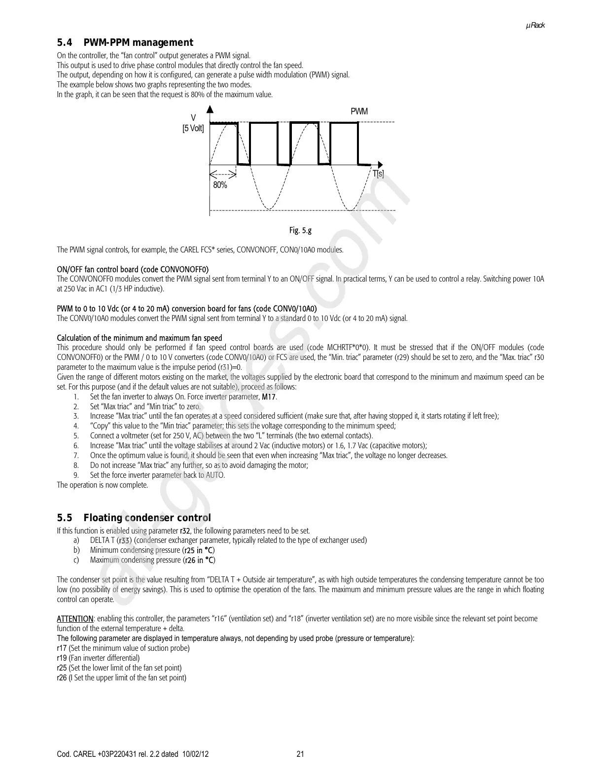
The example below shows two graphs representing the two modes.
In the graph, it can be seen that the request is 80% of the maximum value.
PWM
V
[5 Volt]
T[s]
80%
Fig. 5.g
The PWM signal controls, for example, the CAREL FCS* series, CONVONOFF, CON0/10A0 modules.
ON/OFF fan control board (code CONVONOFF0)
The CONVONOFF0 modules convert the PWM signal sent from terminal Y to an ON/OFF signal. In practical terms, Y can be used to control a relay. Switching power 10A
at 250 Vac in AC1 (1/3 HP inductive).
PWM to 0 to 10 Vdc (or 4 to 20 mA) conversion board for fans (code CONV0/10A0)
The CONV0/10A0 modules convert the PWM signal sent from terminal Y to a standard 0 to 10 Vdc (or 4 to 20 mA) signal.
Calculation of the minimum and maximum fan speed
This procedure should only be performed if fan speed control boards are used (code MCHRTF*0*0). It must be stressed that if the ON/OFF modules (code
CONVONOFF0) or the PWM / 0 to 10 V converters (code CONV0/10A0) or FCS are used, the “Min. triac” parameter (r29) should be set to zero, and the “Max. triac” r30
parameter to the maximum value is the impulse period (r31)=0.
Given the range of different motors existing on the market, the voltages supplied by the electronic board that correspond to the minimum and maximum speed can be
set. For this purpose (and if the default values are not suitable), proceed as follows:
1. Set the fan inverter to always On. Force inverter parameter, M17.
2. Set “Max triac” and “Min triac” to zero.
3. Increase “Max triac” until the fan operates at a speed considered sufficient (make sure that, after having stopped it, it starts rotating if left free);
4. “Copy” this value to the “Min triac” parameter; this sets the voltage corresponding to the minimum speed;
5. Connect a voltmeter (set for 250 V, AC) between the two “L” terminals (the two external contacts).
6. Increase “Max triac” until the voltage stabilises at around 2 Vac (inductive motors) or 1.6, 1.7 Vac (capacitive motors);
7. Once the optimum value is found, it should be seen that even when increasing “Max triac”, the voltage no longer decreases.
8. Do not increase “Max triac” any further, so as to avoid damaging the motor;
9. Set the force inverter parameter back to AUTO.
The operation is now complete.
5.5 Floating condenser control
If this function is enabled using parameter r32, the following parameters need to be set.
a) DELTA T (r33) (condenser exchanger parameter, typically related to the type of exchanger used)
b) Minimum condensing pressure (r25 in °C)
c) Maximum condensing pressure (r26 in °C)
The condenser set point is the value resulting from “DELTA T + Outside air temperature”, as with high outside temperatures the condensing temperature cannot be too
low (no possibility of energy savings). This is used to optimise the operation of the fans. The maximum and minimum pressure values are the range in which floating
control can operate.
ATTENTION: enabling this controller, the parameters “r16” (ventilation set) and “r18” (inverter ventilation set) are no more visibile since the relevant set point become
function of the external temperature + delta.
The following parameter are displayed in temperature always, not depending by used probe (pressure or temperature):
r17 (
Set the minimum value of suction probe)
r19 (
Fan inverter differential)
r25 (
Set the lower limit of the fan set point)
r26 (l Set the upper limit of the fan set point)