ed), as shown in the photo here - as it is directly above the exhaust ducting and could be dam-
aged if you have any accidental wet-starts or similar.
Rudder
The rudder is cut loose, hinged and the dual phenolic con-
trol horns are installed at the factory, and you just need to
fit the rudder servo and linkage.
Servo Choice: Any standard sized minimum 8kg torque
digital servo will be OK for the rudder, but we highly rec-
ommend the JR8311 or 8411.
Centre the rudder servo using your R/C, and fit a plastic
HD (Heavy Duty) servo arm. Fit the rudder servo
(JR8311/8411/Futaba S9351) into the plywood servo
mount, with the output shaft towards the back end of the
servo, and screw into place with the 2.9Ø x 13mm sheet-
metal screws provided. As the servo is mounted inverted,
you should fit the brass eyelets upside-down into the rub-
ber grommets on the servo. Cut a small slot (5mm wide) in
the side of the fin in line with your servo output arm, and
lengthen this slot to suit the linkage later.
Glue the 50mm x 100m balsa plate across the fuselage
under the servo, and cover the plate with aluminium tape.
This will give the servo and extension cable some protec-
tion in the case of an accidental hot, or wet, start.
Make up the linkage using the M3 x 120mm all-thread,
steel clevise and nut at servo end, and the M3 ball-link,
and M3 x 16mm bolt and locknut to secure the ball-link
between the dual phenolic horns (see photo P2).
Supplied in the kit is plastic linkage fairing, pre-painted to
match the fin colour, which can be glued in place to cover
the linkage with a couple of drops of CA. (photo right).
Route the rudder and elevator servo extension cables
down one side of the fuselage, and the turbine cables and
fuel/propane tubes down the other side. Secure them so
that they cannot touch the thrust tube. Protect them with
spiral-wrap sleeves, or similar, where they pass through
plywood bulkheads, and especially when they pass
through fibreglass or carbon-fibre parts which could cut
through the cables or tubes in a few seconds.
10
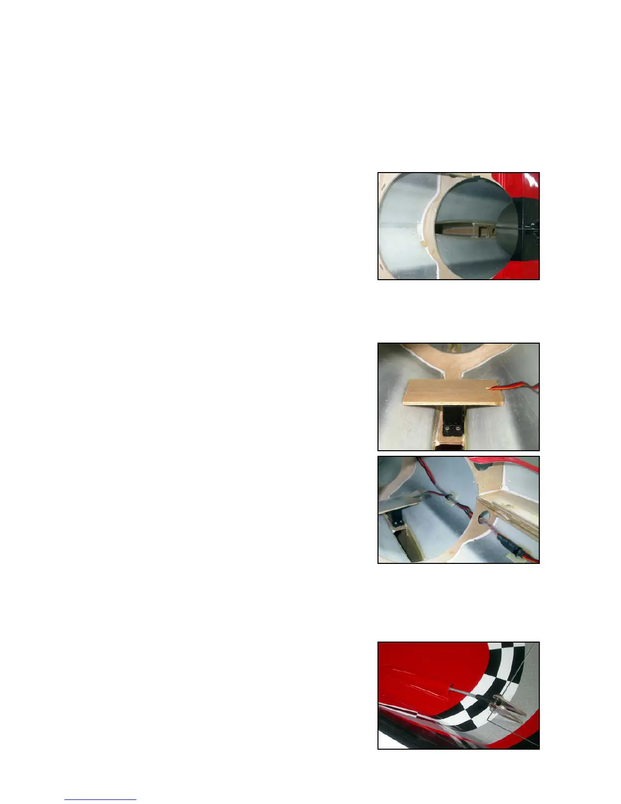
(above) Rudder servo mount is
installed for you at the factory.
(below) Servo installed with balsa
protection glued in position.
(above) Secure rudder & stab
servo extensions to fuselage.
Cover rudder servo plate with alu-
minium tape for heat protection.
(below) Rudder linkage fairing.