211165
4
Vedpak 223_Version 1_09.2019
III. OPERATION
Shortly press MODE button to switch function between DC Voltage, Resistance,
Current, signal frequency and voltage.
Connect the red clip to positive of battery, and black clip to negative of battery.
Auxiliary ground connector is used to connect with the negative of testing
object when it is necessary.
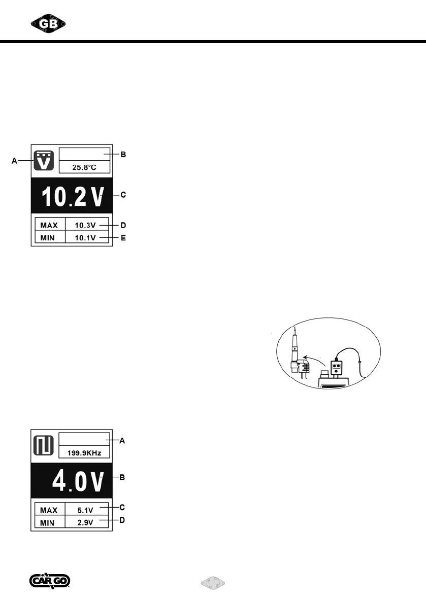
1) DC Voltage Measurement - External Voltage Test
A. DC Voltage Measurement
B. Temperature Measurement
(sensed from thermocouple)
C. DC Voltage Value
D. Max Voltage Value
E. Min Voltage Value
Temp.
CAUTION: Do not press “Power Providing Switch” during DC measurement.
(1) Short press MODE button to switch function to DC Voltage Measurement.
(2) Connecting the testing probe and auxiliary ground connector to the two polarity
of the testing object.
(3) Read the voltage value from the screen.
(4) Read the max and min value of present testing voltage.
(5) If there is a K-type thermocouple sensor on testing
probe, the temperature will be displayed on LCD.
If there is no sensor, the temperature can be
measured by external K-type thermocouple.
2) Signal Frequency and Max/Min Voltage Measurement
A. Frequency Measurement
B. Average Voltage Value
C. Max Voltage Value
D. Min Voltage Value
Frequency
Unplug