211165
5
Vedpak 223_Version 1_09.2019
(1) Short press MODE button to switch function to signal frequency and
Voltage Measurement.
(2) Connecting the auxiliary ground connector to the negative or ground, and probe to
the positive or the testing target.
(3) Read the average voltage value from the screen.
(4) Read the max and min value of present testing voltage.
(5) Read the frequency value of present testing signal.
3) Resistance Measurement
Battery
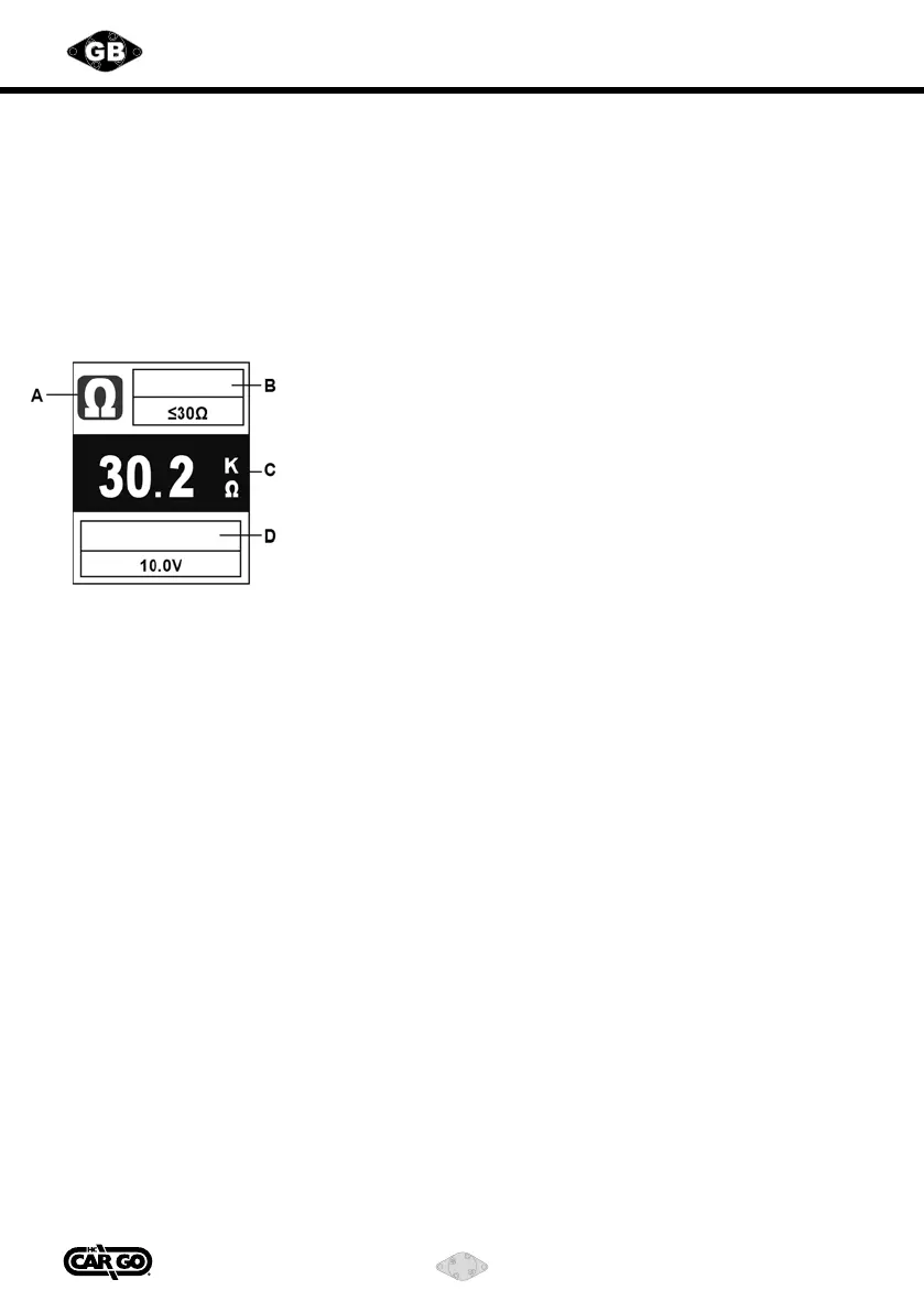
A. Resistance Measurement
B. Max Continuity Value
C. Resistance Value
D. Battery Voltage
(1) In order to prevent electrical hazard, please disconnect the power connection
and resistor, and read the value from the screen.
(2) Short press MODE button to switch function to Resistance Measurement.
(3) Connecting the testing probe and auxiliary ground connector to the two side of
the resistor, and read the value from the screen.
(4) Continuity Test: If the resistance is less than 30 ohms, the buzzer will buzz and
the negative polarity indicator light up (Green Color).
(5) Read the battery value.
4) Testing Power Providing
(This function can be activated any time when the POWER PROVIDING SWITCH
has been pressed.)
(1) Press POWER PROVIDING SWITCH forward, the positive voltage will be sent to the
testing probe, and positive polarity indicator will light up (Red Color).
(2) Press POWER PROVIDING SWITCH backward, negative voltage will be sent to the
testing probe, and negative polarity indicator will light up (Green Color).
(3) The providing voltage value will depend on the supply voltage level. For example,
the providing voltage will be 12V as supply voltage is a 12V battery.
Continuity