TERMINAL BOX
The compressor terminal box is supplied with 2 support plates to
mount the connector for the power wiring conduit. Select the one
support plate with the opening suitable for the size of the conduit
connector to be used and fasten it to the terminal box with the (4)
screws provided.
TERMINAL PLATE WIRING
The parts listed in item #4 (General Comments, pg. 1) are supplied
in parts bag with the compressor and are used when wiring the
terminal plate.
Customer supplied wiring to the compressor terminal plate must be
provided with insulated wire terminal connectors and be suitable for
accommodating the 3/8’’ diameter terminal studs.
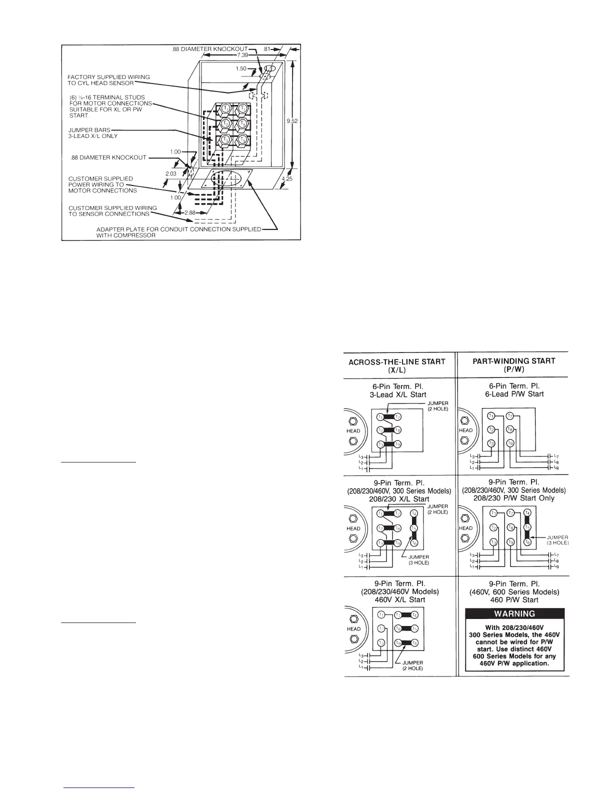
6-Pin Terminal Plate
3-Lead Across-the-Line (X/L) Start (Fig. 3)
The (3) jumper bars supplied with the compressor are required for
3-Lead XL start only. Jumpers are assembled directly on terminal
studs connecting T1 & T7, T2 & T8 and T3 & T9. The 3 power leads
are to be assembled to the applicable terminal stud directly on top of
the jumper bar. Secure wire terminals and jumper bars to the termi-
nal studs with the (6) 3/8-16 jam nuts provided with the compressor.
Torque jam nuts to 12 lb-ft (16 n-m) maximum.
6-Lead Part Winding (P/W) Start (Fig. 3)
The 6 power leads are to be assembled and secured to the applicable
terminal studs with the (6) 3/8-6 jam nuts provided with the compres-
sor. Torque jam nuts to 12 lb-ft (16 n-m) maximum.
Note: Jumper bars are not required with 6-Lead X/L or P/W start
applications.
9-Pin Terminal Plate
208/230 V-3-60 or 200 V-3-50 Across-the-Line Start (Fig. 3)
1. Install (3) 2-hole copper jumper bars connecting terminals 1 to 7,
2 to 6, and 3 to 9.
2. Remove plastic connector block from terminals 4, 5 and 6.
3. Install the fl at connector block (non-conducting) on terminals 4,
5 and 6.
4. Reinstall terminal nuts on terminals 4, 5 and 6 (removed in
step #2).
5. Install the 3-hole copper jumper bar connecting terminals 4, 5
and 6.
6. Connect the line leads to terminals 1, 2 and 3.
7. Install (9) terminal nuts (included in this kit) on terminal studs to
secure jumper bar/line connections. Tighten terminal nuts to 12 ft-lbs
(16 n-m) maximum.
208/230 V-3-60 or 200 V-3-50 Part Winding Start (Fig. 3)
1. Remove plastic connector block from terminals 4, 5 and 6.
2. Install the fl at connector block (non-conducting) on terminals 4,
5 and 6.
3. Re-install terminal nuts on terminals 4, 5 and 6 (removed in
step #1).
4. Install the 3-hole copper jumper bar connecting terminals 4, 5
and 6.
5. Connect the line leads to terminals 1, 2, 3, 7, 8 and 9.
6. Install (9) terminal nuts (included in this kit) on terminal studs to
secure jumper bar/line connections. Tighten terminal nuts to 12 ft-lbs
(16 n-m) maximum.
460 V-3-60 or 400 V-3-50 Across-the-Line Start (Fig. 3)
1. Install (3) 2-hole copper jumper bars connecting terminals 7 to 4,
8 to 5, and 9 to 6.
2. Connect the line leads to terminals 1, 2 and 3.
3. Install (9) terminal nuts (included in this kit) on terminal studs to
secure jumper bar/line connections. Tighten terminal nuts to 12 ft-lbs
(16 n-m) maximum.
Figure A
Terminal Box Arrangement
Figure 3
Terminal Plate Wiring

 Loading...


