Do you have a question about the Carrier 120 Series and is the answer not in the manual?
Details hazards like carbon monoxide poisoning, explosion, fire, and electrical shock.
Warns about fire hazards from combustible materials and vapors.
Discusses potential damage to unit components from improper installation or service.
Warns about sharp edges and burrs on sheet metal parts during handling.
Lists safety standards like NFGC, NFPA 54, ANSI Z223.1, and CSA standards.
Details codes for general installation practices in the US and Canada.
Refers to codes for air for combustion and ventilation requirements.
Lists standards for duct system design and installation.
Refers to standards for acoustical lining and fibrous glass ducts.
Outlines codes for gas piping installation and pressure testing.
Refers to electrical codes such as NEC and CSA.
Lists standards for condensate drain connections.
Warns of potential component damage from electrostatic discharge.
Warns about hazards from improper use or installation, leading to component failure.
Hazards when installing in a residential garage or hazardous atmosphere building.
Hazards from corrosive or contaminated air affecting heat exchangers.
Warning against installing the furnace on its back or hanging it incorrectly.
Explains direct vent and ventilated combustion air options.
Notes no special provisions for combustion air in direct vent systems.
Details requirements for ventilated combustion air systems.
Warns about corrosive air affecting heat exchangers.
Warns about negative pressure conditions and the need for make-up air.
Notes no relocation needed for upflow orientation.
Details relocation requirements for downflow orientation.
Explains repositioning for horizontal orientation.
Warns about freezing risks and necessary protection measures.
Warns about property damage from burst pipes due to condensate.
Describes condensate trap location and drain routing for upflow/downflow.
Details installation requirements for upflow configuration.
Instructions for removing the bottom closure panel for return air.
Notes panel requirement for side return air, and configuration limitations.
Warns about operating furnace without a filter or with access doors removed.
Details approved accessories for downflow supply air connections.
Instructions on connecting return air ducts, prohibiting back connection.
Steps to remove the bottom closure panel for return air.
Hazards from improper furnace orientation or return air duct connection.
Requirement for drain pan in attic or over finished ceiling applications.
Guidelines for constructing a platform to support the furnace.
Instructions for supporting the furnace using threaded rod and angle iron.
Requirement for sheet metal for flame roll-out protection.
Details connection of supply air ducts to furnace or coil casing.
Steps to remove the bottom closure panel for return air.
Notes panel requirement for side return air, and configuration limitations.
Warns about operating furnace without a filter or with access doors removed.
Discusses duct design, sizing, and sealing according to standards.
Refers to filter selection and duct sizing for proper return airflow.
Details requirements for internal acoustical lining or fibrous ductwork.
Warns about gas purging, leak testing, and using proper pipe length.
Emphasizes using new, listed flexible connectors and proper black iron pipe installation.
Warns about keeping gas valve inlet capped and installing a sediment trap.
Stresses adhering to codes and using a separate gas supply line.
Details Massachusetts-specific requirements for gas piping connections.
Warns about gas purging, leak testing, and using proper pipe length.
Emphasizes the need for proper grounding and avoiding electrical faults.
Warns about bypassing the blower door switch, which controls power.
Highlights the importance of uninterrupted ground connection for safety.
Caution regarding intermittent operation if furnace control is not properly grounded.
Warns against using aluminum wire and stresses using copper wire.
Hazards related to manual disconnect switch installation and damage to components.
Instructions for mounting an external electrical box to the furnace casing.
Steps for installing a power cord into the furnace J-Box.
Steps for installing BX cable into the furnace J-Box.
Instructions for making field 24-V connections at the terminal strip.
Lists accessories like Electronic Air Cleaner and Humidifier.
Details Canadian venting code requirements and material specifications.
Mentions Alberta/Saskatchewan requirements and local codes.
Recommends support for sidewall or rooftop vent terminations.
Discusses pipe sizing based on National codes and manufacturer data.
Reiterates CO hazard and safe venting practices.
Explains vent termination and combustion air pipe routing for this system.
Details minimum unobstructed distances for vent terminations in these provinces.
Step-by-step calculation for TEVL using PVC/ABS vent piping.
Calculation for TEVL using polypropylene vent piping, including corrections.
Warns about routing pipes through the furnace and sealing the blower compartment.
Warns against using cement for polypropylene venting systems.
Reinforces not using cement for polypropylene systems and proper coupling use.
Emphasizes using same-manufacturer venting materials.
Requirements for roof flashing and termination kits.
Instructions for installing concentric vent terminations and clearances.
Instructions for installing two-pipe and single-pipe vent terminals.
Recommends support for sidewall or rooftop vent terminations.
Instructions for installing concentric vent terminations on sidewalls.
Step-by-step calculation for TEVL using PVC/ABS vent piping.
Calculation for TEVL using polypropylene vent piping, including corrections.
Warns about routing pipes through the furnace and sealing the blower compartment.
Discusses duct design, sizing, and sealing according to standards.
Refers to filter selection and duct sizing for proper return airflow.
Details requirements for internal acoustical lining or fibrous ductwork.
Warns about gas purging, leak testing, and using proper pipe length.
Emphasizes using new, listed flexible connectors and proper black iron pipe installation.
Warns about keeping gas valve inlet capped and installing a sediment trap.
Stresses adhering to codes and using a separate gas supply line.
Details Massachusetts-specific requirements for gas piping connections.
Warns about gas purging, leak testing, and using proper pipe length.
Emphasizes the need for proper grounding and avoiding electrical faults.
Warns about bypassing the blower door switch, which controls power.
Highlights the importance of uninterrupted ground connection for safety.
Caution regarding intermittent operation if furnace control is not properly grounded.
Warns against using aluminum wire and stresses using copper wire.
Hazards related to manual disconnect switch installation and damage to components.
Instructions for mounting an external electrical box to the furnace casing.
Steps for installing a power cord into the furnace J-Box.
Steps for installing BX cable into the furnace J-Box.
Instructions for making field 24-V connections at the terminal strip.
Lists accessories like Electronic Air Cleaner and Humidifier.
Details Canadian venting code requirements and material specifications.
Mentions Alberta/Saskatchewan requirements and local codes.
Recommends support for sidewall or rooftop vent terminations.
Discusses pipe sizing based on National codes and manufacturer data.
Reiterates CO hazard and safe venting practices.
Explains vent termination and combustion air pipe routing for this system.
Details minimum unobstructed distances for vent terminations in these provinces.
Step-by-step calculation for TEVL using PVC/ABS vent piping.
Calculation for TEVL using polypropylene vent piping, including corrections.
Warns about routing pipes through the furnace and sealing the blower compartment.
Warns against using cement for polypropylene venting systems.
Reinforces not using cement for polypropylene systems and proper coupling use.
Emphasizes using same-manufacturer venting materials.
Requirements for roof flashing and termination kits.
Instructions for installing concentric vent terminations and clearances.
Instructions for installing two-pipe and single-pipe vent terminals.
Recommends support for sidewall or rooftop vent terminations.
Instructions for installing concentric vent terminations on sidewalls.
Step-by-step calculation for TEVL using PVC/ABS vent piping.
Calculation for TEVL using polypropylene vent piping, including corrections.
Notes on initial procedures like checking manifold pressure and temperature rise.
General checks for power supply, thermostat wiring, gas pressure, and blower door.
Warns about intermittent operation or dissatisfaction due to improper setup.
Explains the purpose and location of setup switches for configuration.
Details the function of SW1 switches for application requirements.
Explains SW2 switches for matching furnace airflow to cooling requirements.
Details SW3 switches for selecting continuous fan or low-cooling airflow.
Explains SW4 switches for intermediate heat and airflow adjustments.
Warns about CO poisoning if the trap is not primed or used correctly.
Caution regarding intermittent operation if condensate trap is not primed.
Warns about purging gas lines and testing for leaks.
Warns against forcing gas valve adjusting screw, which can damage it.
Warns against forcing gas valve adjusting screw, impacting manifold pressure.
Caution against redrilling orifices, which can cause noise and flame issues.
Notes on orifice size verification and checking inlet gas pressure.
Notes on manifold pressure adjustment and altitude derating.
Emphasizes that only trained personnel should perform maintenance.
Instructions for proper disposal of components and materials.
Stresses locking out power and tagging switches before servicing.
Warns about improper furnace operation due to wiring errors.
Warns about multiple electrical supplies and the need to lock out power.
Suggests using the Troubleshooting Guide for isolating operation problems.
Instructions on how to retrieve stored fault codes from the control.
Warns about electrical shock from exposed components when closing the blower door switch.
Lists materials to avoid storing near the furnace due to fire/explosion risk.
Stresses locking out power before performing maintenance or service.
Warns against operating without a filter or with access doors removed.
Warns about sharp edges on sheet metal parts.
Warns against operating without a filter or with access doors removed.
Stresses locking out power before performing maintenance or service.
Stresses locking out power before performing maintenance or service.
Stresses locking out power before performing maintenance or service.
Procedure for cleaning the primary heat exchangers.
Stresses locking out power before performing maintenance or service.
Stresses locking out power before performing maintenance or service.
Warns about freeze protection measures for furnaces in unconditioned spaces.
Warns against using ethylene glycol, which can damage plastic components.
Warns about intermittent operation if furnace control is not grounded.
Explains operation with a communicating wall control.
Details operation with a single-stage thermostat in adaptive mode.
Describes the inducer prepurge period and RPM evaluation.
Details the igniter warm-up period and its function.
Explains the trial-for-ignition sequence and flame proving.
Describes the flame proving process and furnace control actions.
Operation with a two-stage thermostat for minimum/maximum heating.
Describes transition from maximum to minimum heat.
Operation with a single-speed thermostat for cooling.
Operation with a single-stage thermostat for two-speed cooling.
Operation with a two-stage thermostat for two-speed cooling.
Explains the dehumidification mode operation.
Low cooling operation with dehumidify demand.
High cooling operation with dehumidify demand.
Cooling off-delay adjustment for dehumidify demand.
Low cooling operation in super-dehumidify mode.
High cooling operation in super-dehumidify mode.
Cooling off-delay adjustment in super-dehumidify mode.
How to select continuous blower speeds using the thermostat.
Refers to instructions on page 79 for component self-test.
Operation with a single-speed thermostat for cooling.
Operation with a single-stage thermostat for two-speed cooling.
Operation with a two-stage thermostat for two-speed cooling.
Explains the dehumidification mode operation.
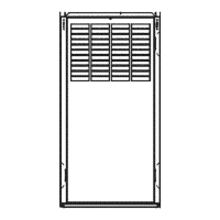
Lists replacement parts for the furnace casing.
Lists replacement parts for the electrical system.
Lists replacement parts for the blower assembly.
Lists replacement parts for the filter system.
Lists replacement parts for the gas control system.
Lists replacement parts for heat exchangers and related components.
Lists replacement parts for the inducer assembly.
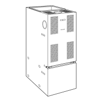
Explains the model nomenclature and specifications.
General warning about using only factory-authorized parts for modifications.
| Stages | Single-Stage |
|---|---|
| Ignition Type | Hot Surface Ignition |
| Heat Exchanger Material | Aluminized Steel |
| Fuel Type | Gas |
| Efficiency | 80% AFUE |
| Heating Capacity | 40, 000 to 130, 000 BTU/h |
| Blower Motor Type | PSC |
| Vent Type | Natural Draft |