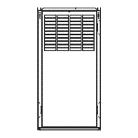
UNIT BLOWER
SBZE SPEED
High
105o12 Med-High
Med-Low
Low
High
120o20 Med-High
Med-Low
Low
NOTES:
Table 12--Airflow Data (CF/vl)
EXTERNAL STATIC PRESSURE IN. WC
0.2 0.3 0.4 0.5 0.6 0.7 0.8 0.9
1425 1350 1305 1250 1170 1030 925 805
1130 1045 1000 950 885 820 745 670
840 810 770 740 685 635 580 509
725 730 740 745 730 715 690 665
2080 2041 1965 1864 1702 1576 1474 1336
1892 1859 1770 1675 1550 1449 1330 1217
1556 1475 1394 1318 1211 1134 1051 938
1221 1164 1081 998 926 855 782 653
1. Airflow values in cubic fi per minute (CFM) rounded to nearest 5 CFM.
2. Data taken with Nters in place
MAINTENANCE
The ability to properly per%tin maintenance on this equip°
ment requires certain expertise, mechanical skills, tools, and
equipment If you do not possess these, do not attempt to
perform any maintenance on this equipment other than those
procedures recommended in the User's Manual. FAILETRE
TO FOLLOW THIS WARNING COULD RESULT IN
POSSIBLE DAMAGE TO THIS EQUIPMENT, SERIOUS
PERSONAL INJURY, OR DEATH.
Be%re per%rming any service ftmctions, unless operations
specifically require power to be on, make sure all utilities are
turned off upstream of appliance. Failure to comply with this
warning will cause a fire hazard and/or bodily harm.
iiiiiiii_, iiiiil
To avoid personal injury, make sure electrical supply power
is off before servicing Failure to follow this warning could
lead to electrical shock, fire, or death.
Step l--General
In order to keep this f'umace in good operating condition and to
maintain its wan'anty, the t_umace MUST be serviced on an annual
basis. This servicing includes a nozzle change, a burner inspection,
a visual check of robe passages through flue outlet and cleanout
ports, and a visual inspection of combustion chamber when burner
is removed.
Depending on above inspection, service could also include a
cleaning and vacuuming of heat exchanger robes and possibly the
heat exchanger drum section.
Removal of any heat exchanger components which are sealed by
gaskets requires replacement of gasket.
Failure to replace any heat exchanger gaskets with new
gaskets when any heat exchanger plates or covers are re-
moved could lead to heat exchanger leakage, sooting, and/or
a hazardous condition capable of causing bodily ham_.
This furnace should never be operated without an air filter
Disposable filters should be replaced at least once a year. If
equipped to provide cooling, filters should be replaced a minin-mm
of twice a year Permanent filters should be cleaned at least twice
a year.
ALWAYS KEEP MAIN OIL VALVE TURNED OFF IF
BURNER IS SHUT DOWN FOR AN EXTENDED PERIOD OF
TIME
Step 2--OH Burner
For optimum per%finance, oil burner nozzle should be replaced
once a year. Contact your service technician if you are unsure of
this procedure.
The procedure for nozzle installation and/or replacement is out=
lined in oil burner instrnction manual which came with t_m'nace
AfIer replacement of nozzle, burner should be adjusted in accor=
dance with Combustion Check section of this instruction.
Step 3--Beat Exchanger and Flue Pipe
Ordinarily, it is not necessary to clean heat exchanger or flue pipe
eve_ year, but it is necessary to have your service technician
check unit before each heating season to determine whether
cleaning or replacement of parts is required
If cleaning is necessary, the _bltowing steps should be performed:
1 Turn off all oil and electrical supplies upstleam of furnace
11
r
If _i/rnace has been in operation, some surfaces may be hot
1
Allow time _br unit to cool dox_n personal inju_ will result, j
2 Disconnect flue pipe.
3 Remove flue collar panel located in I'ront part of ftmaace.
4. Remove bafl"le t'rom seconda_ heat exchanger.
5. Disconnect oil line and remove oil burner t'rom Nrnace.
6. Open 2 cleanout doors located in upper part of flout panel of
_,/fnace.
7. Clean secondary tubes, and primary cylinder with stiff brush
and vaCUllnl cleaner.
8. Befbre re-assembly, the heat exchanger and combustion
charnher should be inspected to determine if replacement is
required.
9. After cleaning, replace bane, flue collar plate, oil burner, and
close the 2 cleanout access doors. Reconnect flue pipe and oil
line.
10. Re-adjust burner _br proper operation.
Step 4--Blower Removal
To remove blower t'rom fm'nace:
1. Turn off all oil and electrical supplies upstleam of furnace.
2. Remove burner access and blower door.
3. Remove blower retaining screw (on blower shell:).
 Loading...